Radio frequency accelerator and coupling cavity device thereof

A coupled cavity and resonant cavity technology, applied in the field of radio frequency accelerators and their coupled cavity devices, can solve the problems of large heat generation, cavity temperature change of the coupled cavity, frequency offset of the coupled cavity, etc., to achieve the effect of satisfying stability

Active Publication Date: 2021-05-07
CHINA INSTITUTE OF ATOMIC ENERGY
View PDF4 Cites 0 Cited by
  • Summary
  • Abstract
  • Description
  • Claims
  • Application Information

AI Technical Summary

Problems solved by technology

[0003] Half of the field in the coupling cavity is the standing wave field and the other half is the traveling wave field. During operation, due to the high loss, the heat generation is large, which will easily cause the cavity temperature of the coupling cavity to change, and then the frequency of the coupling cavity will shift. The feeding of the microwave power and the establishment of the accelerating field are affected, so that the beam quality and parameter indicators cannot meet the requirements

Method used


Image

  • Radio frequency accelerator and coupling cavity device thereof
  • Radio frequency accelerator and coupling cavity device thereof
  • Radio frequency accelerator and coupling cavity device thereof

Examples


Embodiment Construction

[0028] In order to make the purpose, technical solution and advantages of the present invention clearer, the technical solution of the present invention will be clearly and completely described below in conjunction with the accompanying drawings of the embodiments of the present invention. Apparently, the described embodiment is one embodiment of the present invention, but not all of them. Based on the described embodiments of the present invention, all other embodiments obtained by persons of ordinary skill in the art without creative efforts shall fall within the protection scope of the present invention.

[0029] It should be noted that, unless otherwise defined, the technical terms or scientific terms used in the present application shall have the usual meanings understood by those skilled in the field of the present invention. If the descriptions such as "first" and "second" are involved in the whole text, the descriptions such as "first" and "second" are only used to dis...


PUM


Abstract

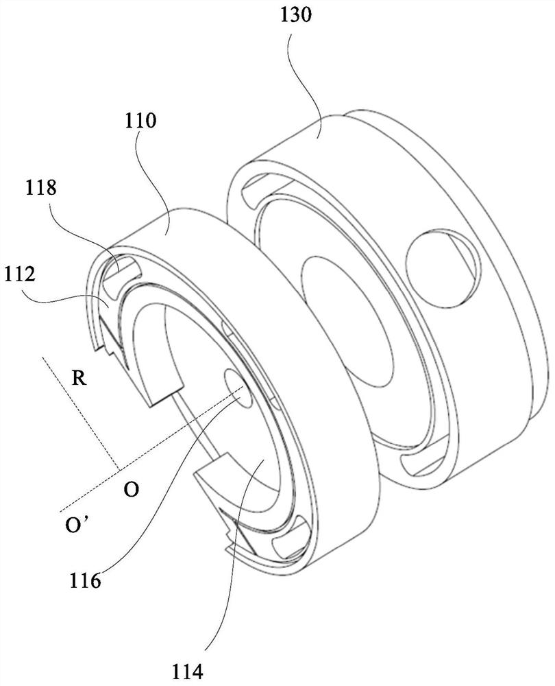
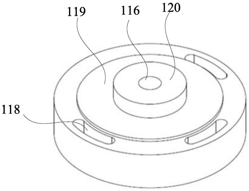
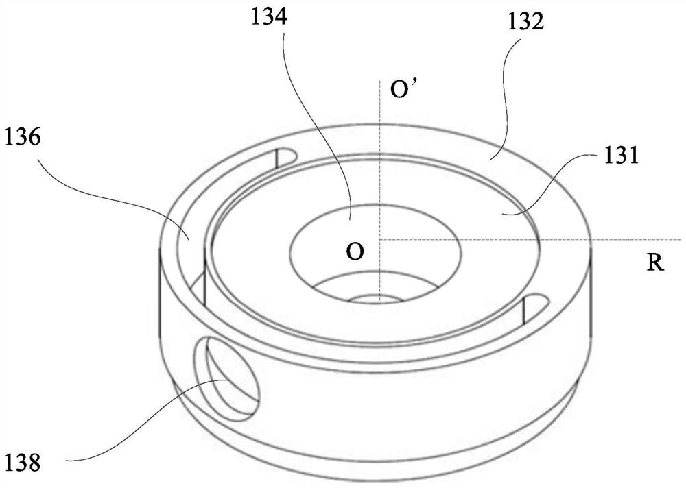
The invention discloses a coupling cavity device which comprises a coupling cavity and a cooling structure, wherein the cooling structure and the coupling cavity are in butt joint along the axis of the coupling cavity. According to the technical scheme, the cooling structure is in butt joint with the coupling cavity along the axis of the coupling cavity, so that the coupling cavity is cooled, and the operation stability of the coupling cavity under higher power is met.

Description

technical field [0001] The invention relates to the technical field of the accelerator field, in particular to a radio frequency accelerator and a coupling cavity device thereof. Background technique [0002] Radio frequency accelerators are generally used to establish microwave acceleration fields in accelerating structures to accelerate charged particles to higher energies. Among them, the microwave electric field can be generated by the microwave source and transmitted to the coupling cavity through the transmission waveguide. After the microwave field mode is converted by the coupling cavity, it enters the accelerating cavity chain to establish an accelerating field that meets the requirements. [0003] Half of the field in the coupling cavity is the standing wave field and the other half is the traveling wave field. During operation, due to the high loss, the heat generation is large, which will easily cause the cavity temperature of the coupling cavity to change, and t...

Claims


Application Information

Patent Timeline
IPC IPC(8): H05H7/00H05K7/20
CPCH05H7/00H05K7/20218
Inventor 杨京鹤韩广文
Owner CHINA INSTITUTE OF ATOMIC ENERGY
Why Eureka
Try Eureka