


Quick Research
Generate reliable direction feasibility study reports for your R&D in just a few steps.

Technical Q&A
Discover and master advanced knowledge NOW. Basics, ideas, possibilities, all at once.

Find Solutions
As an expert in R&D theories, this can generate solutions to your technical problems instantly.

Evaluate Feasibility
Analyze your overall solution with one click, know your potential R&D risks in advance.

Monitor Landscape
Get weekly tech updates, stay abreast of the latest tech innovations and key insights.
Umbrella-shaped pressing mechanism based on large hole
A pressing mechanism and umbrella-shaped technology, which is applied in the direction of grinding workpiece brackets, grinding machines, metal processing equipment, etc., can solve the problems of irregular shape of the workpiece, and achieve the effect of easy handover and manufacturing, satisfying stability, and saving production costs
- Summary
- Abstract
- Description
- Claims
- Application Information
AI Technical Summary
Problems solved by technology
Method used
Image

Examples
Embodiment 1
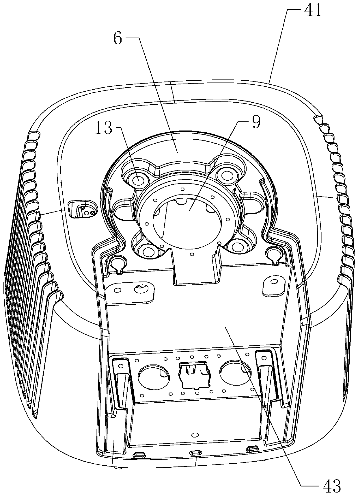
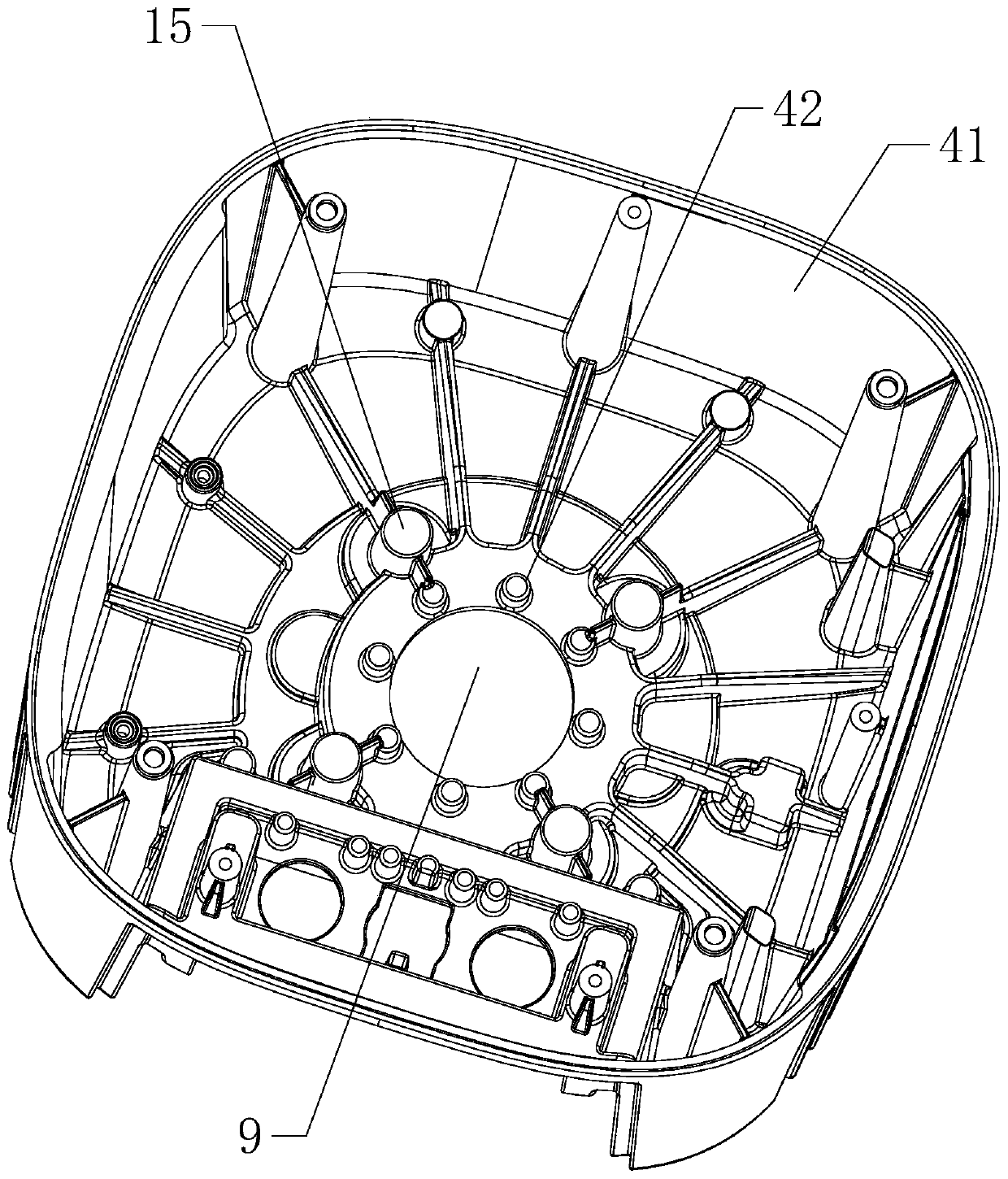
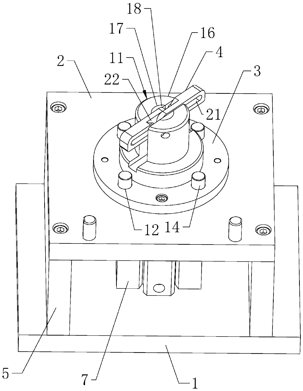
[0039] The invention discloses an umbrella-shaped pressing mechanism based on a large hole, such as image 3 , Figure 4 with Figure 5 As shown, it includes a base 1, a bearing plate 2, a matching stepped platform 3 and two pressing plates 4, the bearing platform 2 is arranged on the upper surface of the base 1 through two opposite vertical plates 5, and the matching stepped platform 3 runs through A protruding groove 12 opposite to the processing hole groove 13 is provided, and a positioning column 14 that passes through the protruding groove 12 and is inserted into the processing hole groove 13 is provided on the bearing platform 2, and is arranged on the bearing platform in cooperation with the stepped platform 3 The upper surface of 2 is in contact with the processing stepped groove 6. When the workpiece is placed on the bearing plate 2, the stepped platform 3 is inserted into the processing stepped groove 6, so that the workpiece can be placed stably, and the positionin...
Embodiment 2
[0048] An umbrella-shaped hold-down mechanism based on large holes, such as Figure 8 with Figure 9 As shown, the difference between the second embodiment and the first embodiment is that the outer wall of the half-ring platform 16 is provided with a sliding plate groove 30 extending to the peripheral wall of the fixed point hole groove 25 (the present invention is preferably arranged on the top wall), Sliding in the sliding plate groove 30 is provided with the sealing plate 31 that is used to close the fixed-point hole groove 25 notches, in case the fixed-point slide bar 44 slips out from the fixed-point hole groove 25 during use, on the outer side wall of the half-ring platform 16 An adjustment groove 32 located on one side of the sliding plate groove 30 is provided (the present invention is preferably provided on the top wall), and the sliding plate groove 30 and the adjusting groove 32 extend in the same direction (the present invention preferably extends along the vertic...
PUM
 Abstract
Description
Claims
Application Information
 - R&D Engineer
- R&D Manager
- IP Professional
- Industry Leading Data Capabilities
- Powerful AI technology
- Patent DNA Extraction
Browse by: Latest US Patents, China's latest patents, Technical Efficacy Thesaurus, Application Domain, Technology Topic, Popular Technical Reports.
© 2024 PatSnap. All rights reserved.Legal|Privacy policy|Modern Slavery Act Transparency Statement|Sitemap|About US| Contact US: help@patsnap.com