
Folding and forming coil, power inductor using the same, and inductance processing method

A technology for forming coils and power inductors, applied in inductors, fixed inductors, fixed signal inductors, etc., can solve the problems that the processing effect is difficult to achieve expectations, the coil pin part is difficult to be flattened, and the cost is high, and the volume And the effect of occupied space compression, various implementation methods, and low difficulty

Active Publication Date: 2022-07-26
TRIO TECH SUZHOU
View PDF4 Cites 0 Cited by
  • Summary
  • Abstract
  • Description
  • Claims
  • Application Information

AI Technical Summary

Problems solved by technology

However, in the actual processing process, due to the precision of the inductance device, it is difficult to flatten the coil pin part, the cost is high, and the final processing effect is difficult to meet expectations.

Method used


Image

  • Folding and forming coil, power inductor using the same, and inductance processing method
  • Folding and forming coil, power inductor using the same, and inductance processing method
  • Folding and forming coil, power inductor using the same, and inductance processing method

Examples


Embodiment 1

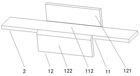
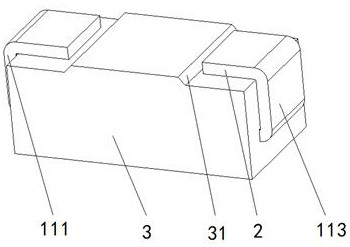
[0058] like Figure 1~Figure 3 As shown, a power inductor is produced by using the above-mentioned folded and formed coil. The power inductor is a horizontal structure and includes an inductance magnet 3 and at least one folded and formed coil disposed inside the inductance magnet 3 . The utility portion 1 of the folded and formed coil includes a first connection segment 111 , a second connection segment 112 and a third connection segment 113 which are connected to each other. Wherein, the first connecting section 111 and the second connecting section 112, the second connecting section 112 and the third connecting section 113 are perpendicular to each other, and the first connecting section 111 and the third connecting section 113 The two are parallel and both are connected to the lead portion 2 of the folded and formed coil, the second connecting section 112 is buried inside the inductance magnet 3, and the edges on both sides of the second connecting section 112 are respecti...

Embodiment 2

[0060] like Figure 4~Figure 6 As shown in the figure, a power inductor is also made of the above-mentioned folded and formed coil. The power inductor is a vertical structure and includes an inductance magnet 3 and at least one folded and formed coil disposed inside the inductance magnet 3 . The utility portion 1 of the folded and formed coil is buried inside the induction magnet 3 , and the utility portion 1 includes a first connection segment 111 , a second connection segment 112 and a third connection segment 113 which are connected to each other. Wherein, the first connecting section 111 and the second connecting section 112, the second connecting section 112 and the third connecting section 113 are perpendicular to each other, and the first connecting section 111 and the third connecting section 113 The two are parallel and connected to the pin part 2 of the folding forming coil, and the first and second folding The widths of both the first folding section 121 and the s...


PUM


Abstract

The invention discloses a folded forming coil, an ultra-low resistance power inductor made by the coil and a processing method of the inductor. The folding forming coil is formed by folding a whole piece of metal sheet, including the utility part and the pin part, and the pin part is connected to both ends of the utility part; The turning position between the segments is tortuous transition, and the equivalent number of turns of the utility part is 3 / 4; in the utility part, at least one lateral edge position of the connecting segment is connected with a folded segment, and each segment of the folded segment is folded and tightly closed at least once. It is attached to the outer peripheral side of the connecting segment connected to it. The invention not only improves the maximum current that the inductance device can withstand, greatly reduces DCR, and improves the stability of use, but also makes the coil structure inside the inductance device simpler, and provides convenience for the processing of the inductance device and its miniaturization application.

Description

technical field [0001] The invention relates to a related processing technology of a power inductor, in particular to a folded forming coil, an ultra-low resistance power inductor made by using the coil, and a processing method of the inductor, belonging to the technical field of inductor processing. Background technique [0002] Inductance is the most common component in electronic equipment, and it is also one of the important components in the circuit. It is widely used in various circuits and can achieve the functions of filtering, energy storage, matching and resonance, especially in the current There are a large number of inductive devices inside some servers and server equipment in the stage. [0003] With the introduction of concepts such as "cloud computing" and "digital city" in recent years, the Internet and Internet of Things technologies have begun to receive widespread attention. The update iterations of various hardware devices are becoming more frequent and d...

Claims


Application Information

Patent Timeline
Patent Type & Authority Patents(China)
IPC IPC(8): H01F27/28H01F27/29H01F37/00H01F41/00H01F41/02
CPCH01F27/2847H01F27/2852H01F27/292H01F37/00H01F41/00H01F41/0246
Inventor 饶金火林伙利
Owner TRIO TECH SUZHOU
Learn More