
Sewage treatment device

A technology of sewage treatment device and aqueduct, which is applied in water/sewage treatment, biological treatment device, biological water/sewage treatment, etc., can solve the problems of requiring personnel and high energy consumption for sewage treatment, and reduce workload and process routes. And specifications and models, easy to deal with the effect of a large amount of sewage

Pending Publication Date: 2021-05-07
GUANGZHOU RESOURCE ENVIRONMENTAL PROTECTION TECH CO LTD +1
View PDF0 Cites 0 Cited by
  • Summary
  • Abstract
  • Description
  • Claims
  • Application Information

AI Technical Summary

Problems solved by technology

[0004] In view of the above problems, the purpose of the present invention is to provide a sewage treatment device to solve the problems of high energy consumption of existing sewage treatment and the need for on-site operation of personnel

Method used


Image

  • Sewage treatment device
  • Sewage treatment device
  • Sewage treatment device

Examples


no. 1 example

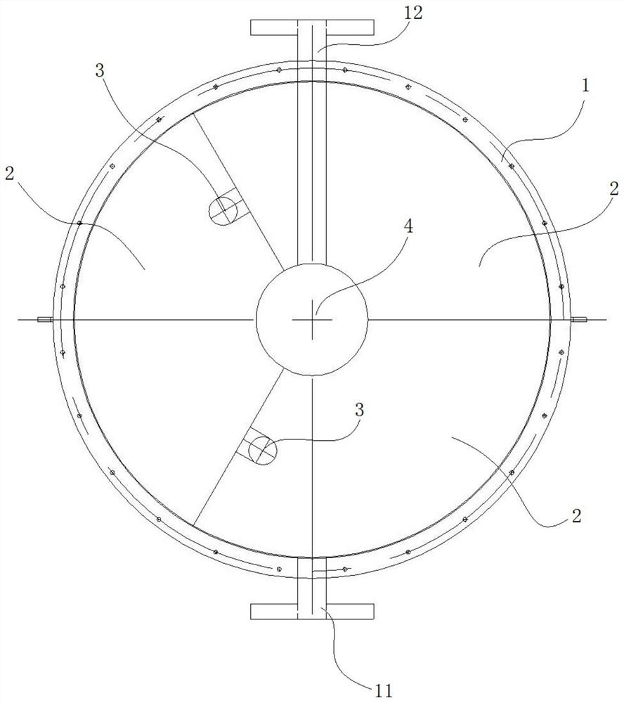
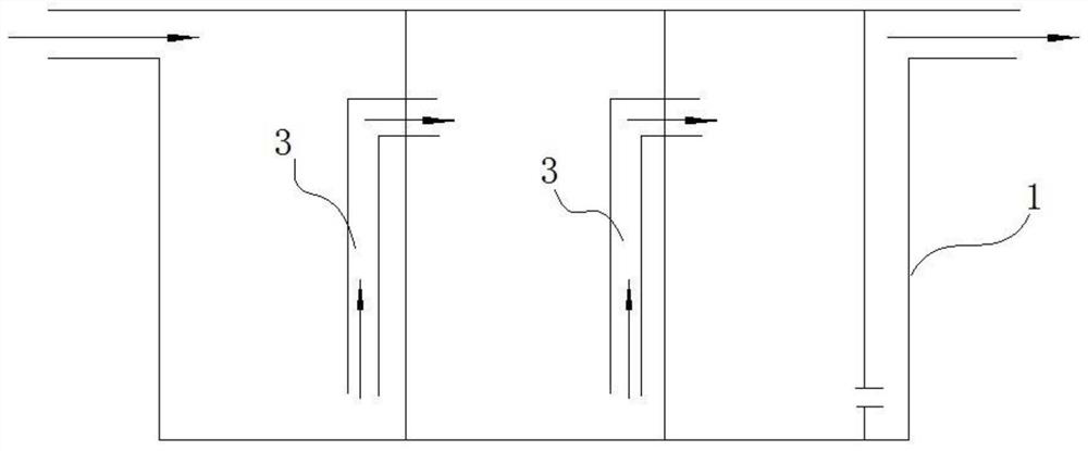
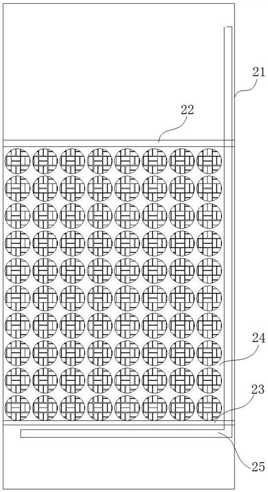
[0029] Such as figure 1 and figure 2 As shown, a sewage treatment device according to an embodiment of the present invention includes a tank body 1 and a plurality of divided buckets 2 arranged in the tank body 1. In this embodiment, three divided buckets 2 are provided, and three Each divided barrel 2 is evenly arranged in the tank body 1, and the barrel walls of adjacent divided barrels 2 are pasted together without welding; in other embodiments, the divided barrels 2 can also be other numbers, preferably, divided The number of grid buckets 2 is greater than or equal to 5; the upper part of the tank body 1 is provided with a water inlet 11 and a water outlet 12, and the water inlet 11 and the water outlet 12 are respectively connected to different grid buckets 2; a plurality of grid buckets 2 The water guide pipe 3 is sequentially communicated, and the first end of the water guide pipe 3 is located at the bottom of a compartment bucket 2, and the second end of the water gu...

no. 2 example

[0041] The difference with the first embodiment is that the number of compartment buckets 2 is different, such as Figure 5 As shown, six compartments 2 are arranged in the tank body 1, and the barrel walls of each compartment 2 are attached together without welding and fixing. Sewage is graded and treated through six compartments 2 .

[0042] To sum up, the embodiment of the present invention provides a sewage treatment device, which sequentially treats the sewage by arranging a plurality of compartments 2 in the tank body 1, and can train the microorganisms in the sewage to form a hierarchical food chain relationship, so that no Personnel are required to maintain and operate on site, and the emissions can reach the standard without being on duty. Moreover, the present invention carries out modular processing on the tank body 1, which facilitates the treatment of a large amount of sewage. The compartment 2 can be manufactured in batches, reducing the process routes and spec...


PUM


Abstract

The invention relates to the technical field of sewage treatment, and discloses a sewage treatment device, which comprises a tank body and a plurality of division barrels arranged in the tank body, wherein a water inlet and a water outlet are formed in the upper part of the tank body; each grid barrel comprises a barrel body, an upper fixed grid and a lower fixed grid, the upper fixed grid and the lower fixed grid are vertically arranged in the barrel body at an interval, a filler layer is arranged between the upper fixed grid and the lower fixed grid, and an aeration pipe is arranged below the lower fixed grid; and the plurality of division barrels are sequentially communicated through a water guide pipe, the first end of the water guide pipe is located at the bottom of one division barrel, and the second end of the water guide pipe is located at the top of the adjacent division barrel. According to the sewage treatment device disclosed by the embodiment of the invention, the sewage is treated in sequence by arranging the plurality of lattice buckets in the tank body, and microorganisms in the sewage can be trained to form a hierarchical food chain relationship, so that the sewage can be discharged up to the standard without staying for maintenance and operation and unattended operation.

Description

technical field [0001] The invention relates to the technical field of sewage treatment, in particular to a sewage treatment device. Background technique [0002] With the rapid economic development, the pollution degree of domestic sewage has gradually deepened, which has become one of the main reasons for water pollution in my country. The treatment process of traditional sewage treatment plants has been unable to meet the needs of environmental protection, for example: A 2 Although the activated sludge method represented by oxidation ditch and SBR has a good and stable treatment effect, it has disadvantages such as large footprint, odor and unsightly appearance to varying degrees, and requires personnel to carry out daily maintenance and operation. . [0003] At present, the agricultural sewage decentralized sewage treatment processes mainly include A0+MBR, MBBR+precipitation and biofilm method+precipitation and other processes. Although these processes have been optimi...

Claims


Application Information

Patent Timeline
Patent Type & Authority Applications(China)
IPC IPC(8): C02F9/14C02F3/30C02F7/00C02F1/00
CPCC02F3/302C02F7/00C02F1/006C02F2101/16C02F2201/007C02F2203/006C02F2209/10C02F2209/08C02F9/20Y02W10/10
Inventor 杨永红王志雄彭义雄翟小燕苏蕾吴闪闪苏玉婷周刚张晓健
Owner GUANGZHOU RESOURCE ENVIRONMENTAL PROTECTION TECH CO LTD
Learn More