
Shaft polishing mechanism

A technology of polishing mechanism and polishing machine, which is applied in the direction of surface polishing machine tools, grinding/polishing equipment, grinding/polishing safety devices, etc., and can solve problems such as safety accidents, loose clamping of equipment, and reduced polishing efficiency

Inactive Publication Date: 2021-05-07
无锡市奥普机械有限公司
View PDF0 Cites 0 Cited by
  • Summary
  • Abstract
  • Description
  • Claims
  • Application Information

AI Technical Summary

Problems solved by technology

[0002] At present, most of the polishing is performed by manual clamping polishing equipment, and manual clamping polishing equipment not only easily makes the surface of the polished object smooth and uneven, but also often causes safety accidents due to insufficient clamping of the equipment during the polishing process , and if rough polishing and fine polishing are to be performed during the polishing process, the polishing blades need to be replaced, which greatly reduces the working efficiency of polishing, and there is seldom the process of adding polishing paste or polishing liquid in the process, which makes After fine polishing, the polishing effect will be reduced, and the products produced are difficult to meet the needs of customers

Method used


Image

  • Shaft polishing mechanism
  • Shaft polishing mechanism

Examples


Embodiment Construction

[0017] The following will clearly and completely describe the technical solutions in the embodiments of the present invention with reference to the accompanying drawings in the embodiments of the present invention. Obviously, the described embodiments are only some, not all, embodiments of the present invention.

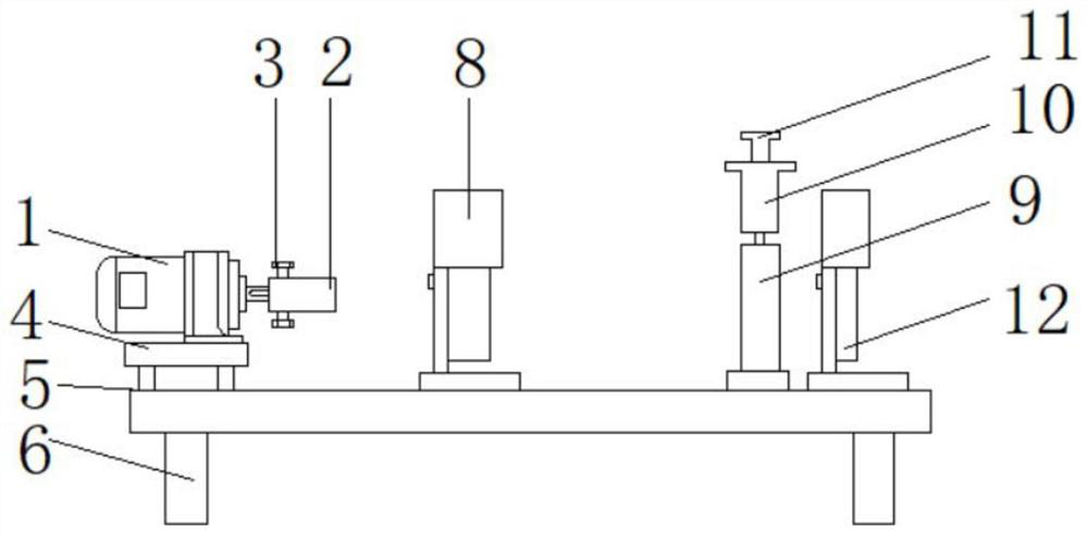
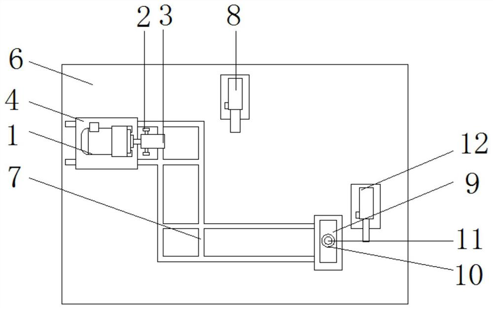
[0018] refer to Figure 1-2 , a polishing mechanism for a shaft, comprising a motor 1 and a workbench 6, the output shaft of the motor 1 is connected with a pinch tube 2, and both sides of the pinch tube 2 are threaded with bolts 3, and one end of the bolt 3 close to the pinch tube 2 is A rubber pad is bonded, the bottom of the motor 1 is connected with a fixed seat 4 by screws, the four corners of the bottom of the fixed seat 4 are welded with blocks 5, and the top of the workbench 6 is provided with a card slot 7, and the top view of the card slot 7 is a Z-shaped structure. And the block 5 is inserted in the slot 7, the diameter of the block 5 matches the height of...


PUM


Abstract

The invention discloses a shaft polishing mechanism. The shaft polishing mechanism comprises a motor and a workbench, wherein an output shaft of the motor is connected with a clamping pipe; the two sides of the clamping pipe are in threaded connection with bolts; the bottom of the motor is connected with a fixed seat through screws; clamping blocks are welded to the four corners of the bottom of the fixed seat; a clamping groove is formed in the top of the workbench; the clamping blocks are inserted into the clamping groove; the center of one side of the top of the workbench is provided with a first polishing machine; the other side of the top of the workbench is provided with a round pipe and a second polishing machine; the top of the round pipe is provided with a through hole; the through hole is connected with a discharging port of a spraying pipe; and a piston rod is inserted into the inner wall of the spraying pipe. The shaft polishing mechanism is simple in structure, but can meet most polishing requirements; the two polishing machines in the shaft polishing mechanism can conduct coarse polishing and fine polishing, so that the effect after polishing is more perfect; and the polishing paste spraying process is further added in the middle, so that the fine polishing effect is better.

Description

technical field [0001] The invention belongs to the technical field of polishing devices, in particular to a shaft polishing mechanism. Background technique [0002] At present, most of the polishing is performed by manual clamping polishing equipment, and manual clamping polishing equipment not only easily makes the surface of the polished object smooth and uneven, but also often causes safety accidents due to insufficient clamping of the equipment during the polishing process , and if rough polishing and fine polishing are to be performed during the polishing process, the polishing blades need to be replaced, which greatly reduces the working efficiency of polishing, and there is seldom the process of adding polishing paste or polishing liquid in the process, which makes After fine polishing, the polishing effect will be reduced, and the products produced are difficult to meet the needs of customers. Contents of the invention [0003] The purpose of the present inventio...

Claims


Application Information

Patent Timeline
IPC IPC(8): B24B29/02B24B27/00B24B55/00B24B41/06B24B57/02
CPCB24B27/0076B24B29/02B24B41/067B24B55/00B24B57/02
Inventor 吴少华
Owner 无锡市奥普机械有限公司
Learn More