
A method for controlling the viscosity stability of magnetorheological fluid

A viscosity stability, magnetorheological fluid technology, used in grinding automatic control devices, manufacturing tools, grinding machine parts and other directions, can solve the problem of inaccurate calculation, improve processing efficiency, improve viscosity control accuracy, Realize the effect of real-time automatic stability control

Active Publication Date: 2016-03-23
四川睿光科技有限责任公司
View PDF7 Cites 0 Cited by
  • Summary
  • Abstract
  • Description
  • Claims
  • Application Information

AI Technical Summary

Problems solved by technology

[0008] Another object of the present invention is to meet the needs of greatly changing the viscosity of the magnetorheological fluid when processing different workpieces. The present invention adjusts the viscosity of the magnetorheological fluid through an off-line control method. The closely related water loss, ambient temperature and humidity, and the precipitation of magnetorheological fluid are used as parameters. After a series of calculations, the frequency of water replenishment, the duration of water replenishment, or the amount of magnetorheological fluid to be added solves the problem that the existing technology cannot accurately calculate the amount of magnetorheological fluid that needs to be added. The amount of water or new magnetorheological fluid causes the actual value of magnetorheological fluid viscosity to oscillate around the target value, and it takes a long time to stabilize, which greatly improves the processing efficiency

Method used


Image

  • A method for controlling the viscosity stability of magnetorheological fluid
  • A method for controlling the viscosity stability of magnetorheological fluid
  • A method for controlling the viscosity stability of magnetorheological fluid

Examples


Embodiment Construction

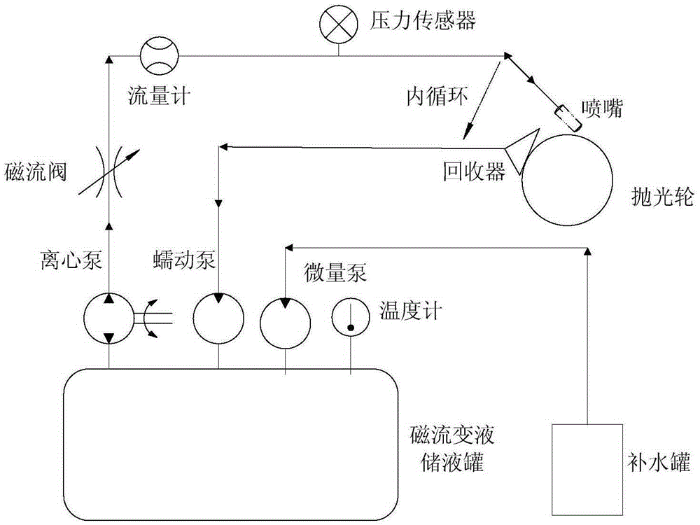
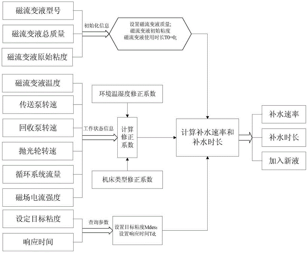
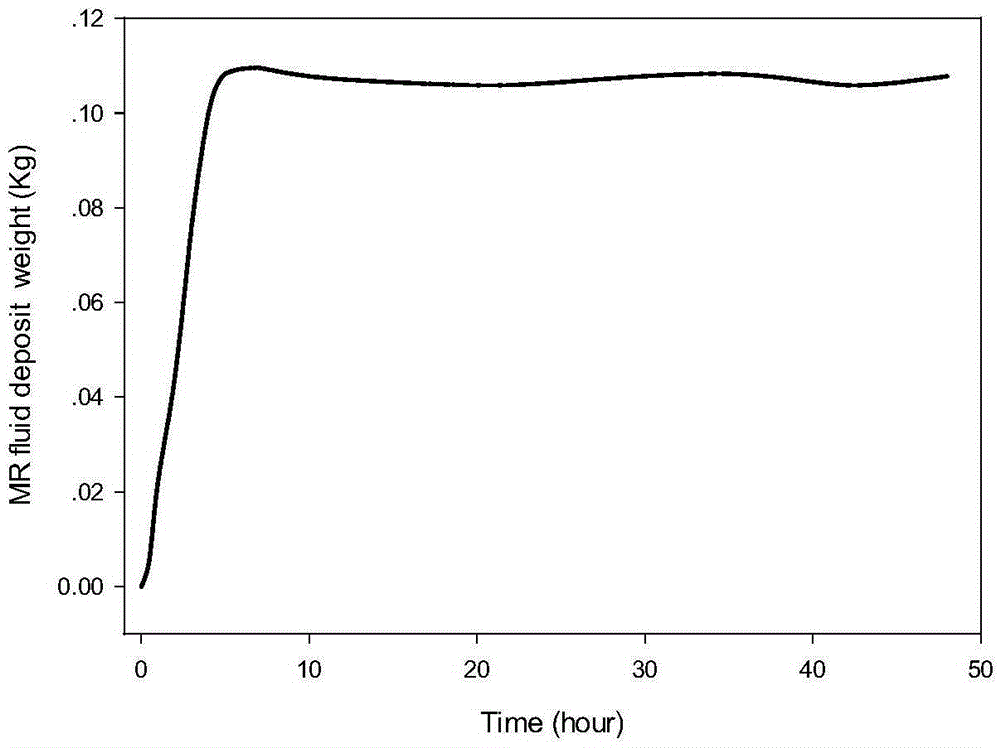
[0043] Attached below Figure 1-4 The present invention is further described in detail so that those skilled in the art can implement it with reference to the description.

[0044] Such as figure 1 Shown, a kind of magnetorheological fluid viscosity stability control method, which comprises the following steps:

[0045] Step 1. Set the target viscosity value μ′ of the magnetorheological fluid in the magnetorheological fluid circulation system as required r ;

[0046] Step 2. Calculation of relative viscosity change rate, according to the current intensity I of the magnetic flow valve in the magnetorheological fluid circulation system, the pipeline pressure P and the pipeline flow Q, calculate the relative viscosity value μ at different consecutive time points r , by calculating the relative viscosity change rate dμ at two adjacent time points r , wherein the formula for calculating the relative viscosity change rate is: d μ r ...


PUM


Abstract

The invention discloses a method for controlling the stability of the viscosity of magnetorheological fluid. The method has the advantages that the relative viscosity of the magnetorheological fluid is computed by the aid of the pressure of pipelines, flow rates of the pipelines and the current intensity of a magnetic current valve, a dynamic algorithm model is built on the basis of relative viscosity computation, accordingly, the viscosity of the magnetorheological fluid can be monitored and regulated in real time, and the stability of the viscosity of the magnetorheological fluid can be accurately and automatically controlled; the precision of the viscosity of the magnetorheological fluid can be within the range of 2% under the control of the method, so that polishing requirements of high-precision optical elements can be met; as the viscosity of the magnetorheological fluid needs to be greatly changed when different workpieces are machined, the viscosity of the magnetorheological fluid can be regulated by the method for controlling the stability of the viscosity of the magnetorheological fluid in an offline manner, the problem that an actual value of the viscosity of magnetorheological fluid fluctuates around a target value and only can be stable after a long time due to incapability of accurately computing the quantity of required-to-be-added water or required-to-be-added magnetorheological fluid in the prior art can be solved, and the machining efficiency can be greatly improved.

Description

technical field [0001] The invention relates to the field of ultra-precision optical element processing, in particular to a method for controlling the viscosity stability of magnetorheological fluid. Background technique [0002] Magneto-rheological polishing technology is an emerging optical surface precision processing technology. It has the characteristics of no sub-surface defects and high processing accuracy. It is widely used in the polishing of large-diameter optical components in strong laser system devices. It belongs to the equipment that is prohibited from being exported to China. The magnetorheological machine tools we use are independently developed and manufactured in China. For example, five-axis four-linkage CNC machine tools can polish flat and curved surfaces and other optical components. The core part of the magnetorheological machine tool is the magnetorheological fluid circulation system. In the circulation system, the magnetorheological fluid enters the...

Claims


Application Information

Patent Timeline
Patent Type & Authority Patents(China)
IPC IPC(8): B24B51/00B24B57/00
CPCB24B1/005B24B51/00B24B57/00
Inventor 唐才学侯晶温圣林张远航颜浩袁志刚郑楠杨春林
Owner 四川睿光科技有限责任公司
Learn More