an electric circular saw

A technology for electric circular saws and saw blades, which is applied in circular saws, portable motor circular saws, sawing machine devices, etc. Heat dissipation efficiency, the effect of ensuring the heat dissipation effect

Active Publication Date: 2022-06-24
NANJING CHERVON IND
View PDF0 Cites 0 Cited by
  • Summary
  • Abstract
  • Description
  • Claims
  • Application Information

AI Technical Summary

Problems solved by technology

However, the cooling air path design of this heat dissipation method is relatively complicated, and the heat dissipation effect of the power board is poor.

Method used


Image

  • an electric circular saw
  • an electric circular saw
  • an electric circular saw

Examples


Embodiment 1

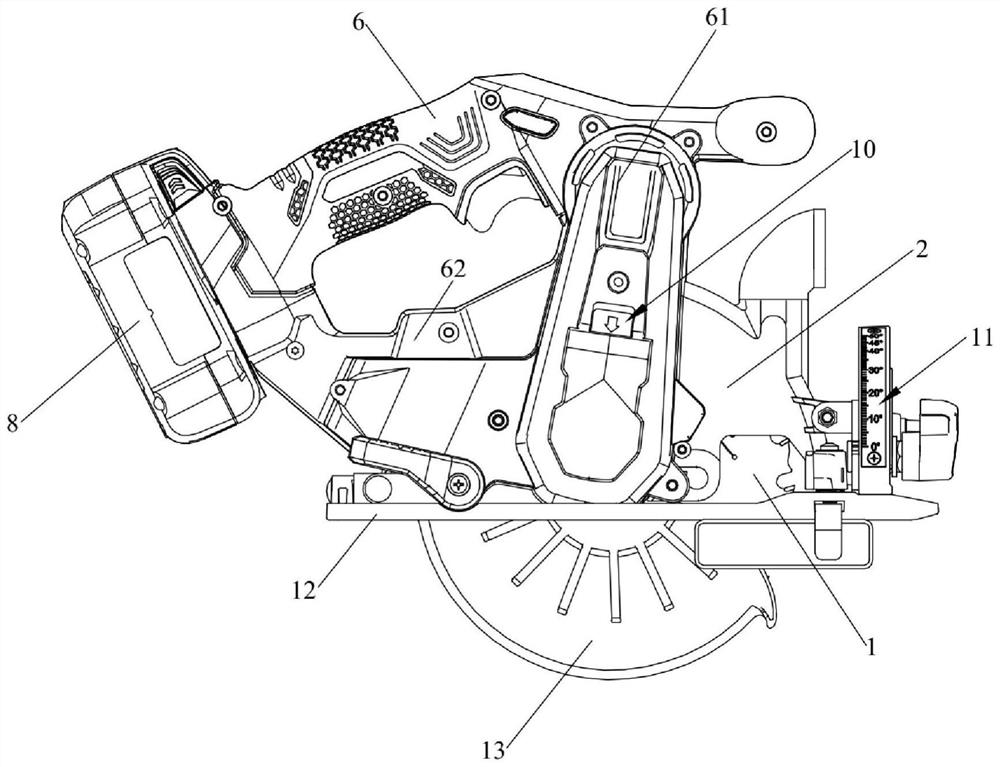
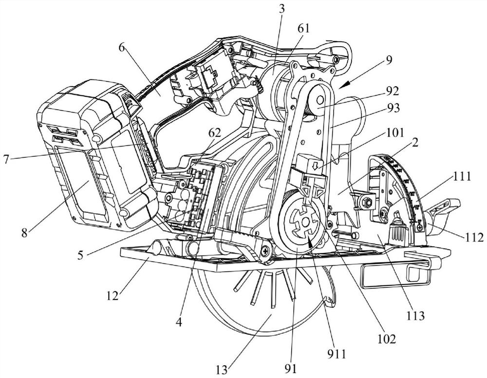
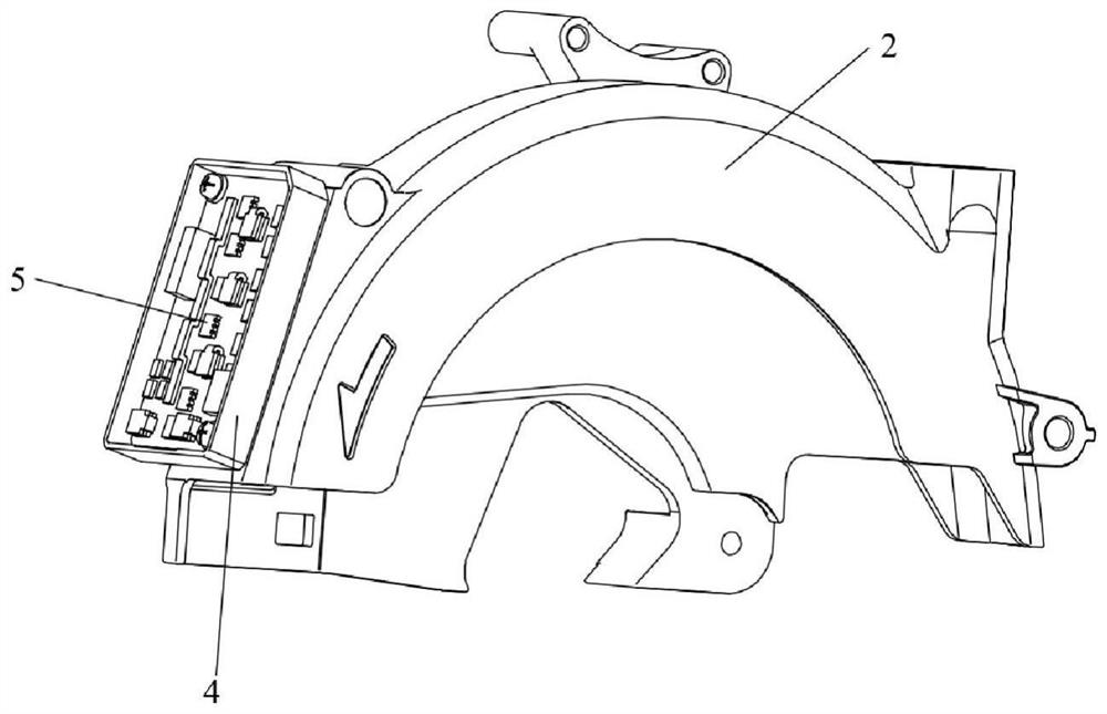
[0058] like Figure 1-Figure 3 As shown, this embodiment provides an electric circular saw, including a saw blade 1 , a fixed shield 2 , a motor 3 , a heat sink 4 , a power board 5 and a casing 6 . Specifically, the casing 6 includes a grip portion for the user to hold. The motor 3 includes an output shaft that rotates around the first axis, and the output shaft is connected to and drives the saw blade 1 ; The heat sink 4 is arranged on the fixed shield 2 , the casing 6 includes a first accommodating part 61 and a second accommodating part 62 arranged at both ends of the casing 6 , the motor 3 is arranged in the first accommodating part 61 , and the heat sink 4 is arranged in the first accommodating part 61 . inside the second accommodating portion 62 . The power board 5 is arranged on the heat sink 4 for controlling the output power of the motor 3 .

[0059]In the electric circular saw provided in this embodiment, the heat sink 4 is arranged on the fixed shield 2 , the fix...

Embodiment 2

[0072] like Figure 4-Figure 6 As shown, this embodiment provides another electric circular saw. The difference between this embodiment and the first embodiment is that the installation positions of the motor 3A and the heat sink 4A are different. Correspondingly, the extension of the transmission belt 93A relative to the fixed shield 2A is The orientation, as well as the position of the locking assembly 10A relative to the stationary shield 2A, has also been adjusted. Specifically, the fixed shield 2A is fixedly connected to the casing 6A, the motor 3A is fixedly arranged in the first accommodating portion 61A of the casing 6A, and is located at the rear of the fixed shield 2A, and the heat sink 4A is arranged on the second side of the casing 6A. Inside the accommodating portion 62A, and located on the upper side of the fixed shield 2A. The cooling air path of the fan flows directly from one side of the motor 3A to the other side of the motor 3A, and the cooling air path of ...


PUM

PropertyMeasurementUnit
thermal conductivityaaaaaaaaaa

Abstract

The invention relates to the technical field of electric tools and discloses an electric circular saw. The electric circular saw includes a saw blade, a fixed guard, a motor, a radiator and a power board. The fixed guard encloses the upper part of the saw blade. The output end of the motor is connected with the saw blade to drive the saw blade to rotate. The heat sink is arranged on the fixed shield, and the casing includes a first housing part and a second housing part arranged at both ends of the cabinet, the motor is arranged in the first housing part, and the heat sink is arranged in the second housing part; On the component, it is used to control the output power of the motor. The electric circular saw provided by the present invention uses the fixed shield to indirectly increase the heat dissipation area of ​​the heat sink, and because the fixed shield is directly in contact with the outside air, the heat dissipation efficiency of the power board can be further improved, and there is no need to install a special cooling air The power board is dissipated through the circuit, so that the cooling air circuit can be simplified.

Description

technical field [0001] The invention relates to the technical field of electric tools, in particular to an electric circular saw. Background technique [0002] A circular saw is a power tool for cutting wood or plastic panels, etc. In the existing electric circular saw, a special cooling air passage is usually provided, and the power board used for controlling the output power of the motor is arranged in the cooling air passage to dissipate heat from the power board. However, the cooling air passage design of this heat dissipation method is relatively complicated, and the heat dissipation effect of the power board is poor. [0003] Therefore, there is an urgent need for a new type of electric circular saw to solve the above technical problems. SUMMARY OF THE INVENTION [0004] The purpose of the present invention is to provide an electric circular saw, which can improve the heat dissipation efficiency of the power board and simplify the cooling air path compared with the...

Claims


Application Information

Patent Timeline
Patent Type & Authority Patents(China)
IPC IPC(8): B27B9/00B27G19/02B23D45/16B23Q11/12B26B25/00
CPCB27B9/00B27G19/02B23D45/16B23Q11/126B26B25/002
Inventor 王洪斌
Owner NANJING CHERVON IND
Why Eureka
Try Eureka