A centrifugal supplementary oil supply device and method based on micropore oil supply

An oil supply device and centrifugal technology, applied in chemical instruments and methods, solid separation, classification, etc., can solve the problems of poor delay effect, low effective oil supply rate, high oil supply rate, etc., and achieve a basic oil supply rate Consistent, meet the long life requirements, the effect of stable oil supply rate

Active Publication Date: 2022-06-24
SHANGHAI AEROSPACE CONTROL TECH INST
View PDF0 Cites 0 Cited by
  • Summary
  • Abstract
  • Description
  • Claims
  • Application Information

AI Technical Summary

Problems solved by technology

[0004] (1) The delay ring is exposed at both axial ends of the oil reservoir. When the bearing rotates at high speed, the lubricating oil overflowing on the surface of the delay ring will randomly splash to the non-lubricating position, pollute the internal cavity, and cause the waste of lubricating oil. The effective oil supply rate is reduced, and the long-term lubrication life is reduced;
[0005] (2) The oil seepage depth of the delay ring structure design is small, and the delay effect mainly depends on the adjustment of four throttle core valves. formula), while the oil supply rate increases, the long-term lubrication life is low, and the oil supply rate is not easy to control;
[0006] (3) The structural design of the oil reservoir and the throttling core valve prevents all the lubricating oil in the oil reservoir from overflowing from the throttling core valve, especially in the low-gravity space environment, resulting in waste of lubricating oil, low utilization rate, and long-term lubrication Reduced lifespan
[0007] Based on the above analysis, it can be seen that this structural design has defects such as excessive oil supply rate and difficult control, large lubricating oil loss, low effective oil supply rate, and low long-term lubrication life.

Method used


Image

  • A centrifugal supplementary oil supply device and method based on micropore oil supply
  • A centrifugal supplementary oil supply device and method based on micropore oil supply
  • A centrifugal supplementary oil supply device and method based on micropore oil supply

Examples


Embodiment Construction

[0036] The present invention will be further described below by describing a preferred specific embodiment in detail with reference to the accompanying drawings.

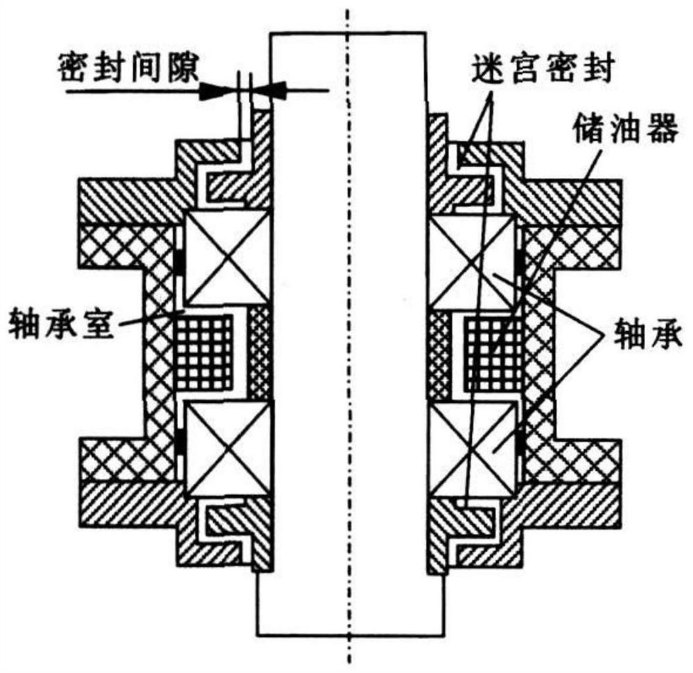
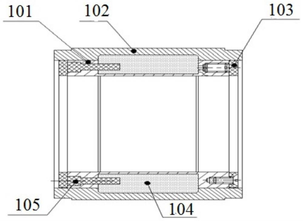
[0037] like image 3 As shown, it is a centrifugal supplementary oil supply device based on micropore oil supply of the present invention, and the positional relationship between the centrifugal supplementary oil supply device and the bearing assembly is the same as that of the bearing assembly. figure 1 The two positions in the bearing system shown are similar.

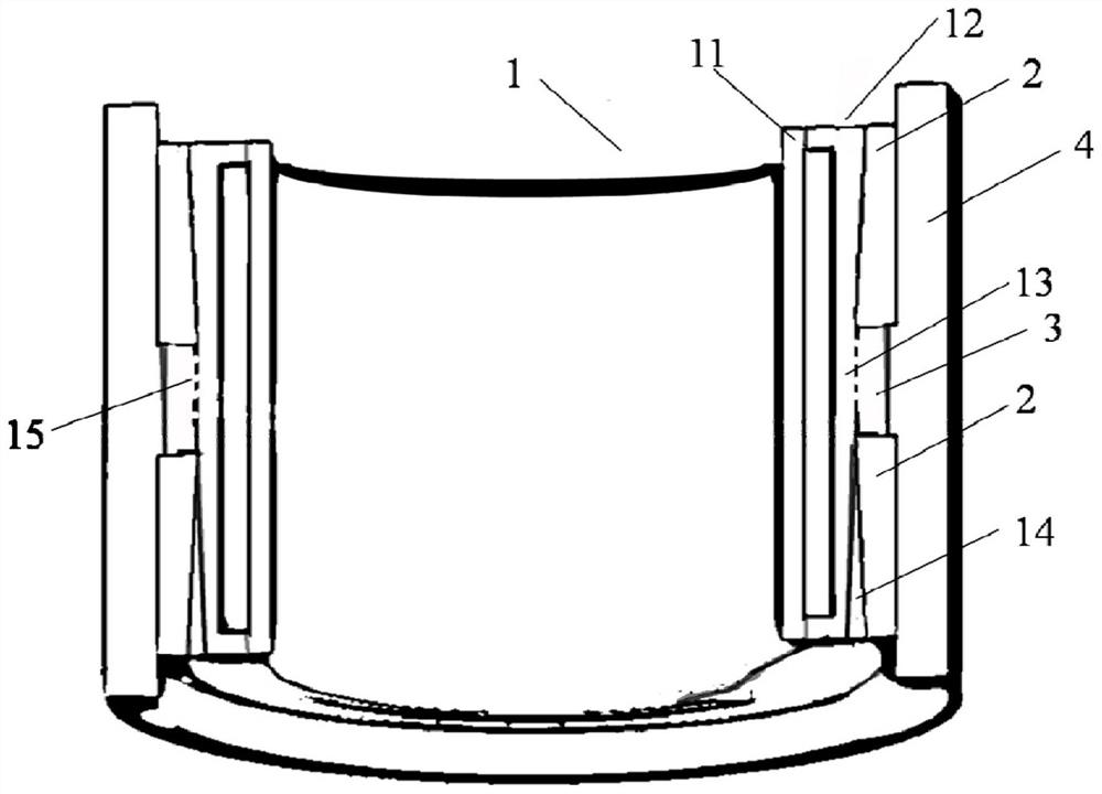
[0038] The centrifugal supplementary oil supply device based on micropore oil supply of the present invention (may be simply referred to as the bearing centrifugal supplementary oil supply device) comprises an oil reservoir 1 and a pair of wedge-shaped delay rings 2 . In this embodiment, the oil reservoir 1 contains lubricating oil. Wherein, each wedge-shaped delay ring 2 is arranged around the outer surface of the oil reservoir 1, the outer side of the ...


PUM


Abstract

The invention discloses a centrifugal supplementary oil supply device and method based on micropore oil supply. The device is suitable for space long-life rolling bearings. The device includes: an oil reservoir; a pair of wedge-shaped delay rings, and each wedge-shaped delay ring It is arranged around the outer surface of the oil reservoir and its outer side is the outer spacer ring of the bearing assembly. There is an oil storage chamber between the two wedge-shaped delay rings. There are several oil supply micro-holes on the outer wall of the oil reservoir at the oil storage chamber, so that The oil in the oil reservoir enters the oil storage cavity from the oil supply micropore, and then is supplied to the bearing assembly through the wedge-shaped delay ring. When the oil in the oil reservoir is large, the oil is stored in the oil storage cavity, and The oil is supplied to the bearing assembly through the wedge-shaped delay ring; when the oil in the oil reservoir is low, the oil stored in the oil storage chamber supplies oil to the wedge-shaped delay ring, and then supplies oil to the bearing assembly. It adopts the micropore oil supply method to control the oil flow rate to stabilize the speed control effect. The wedge-shaped delay ring and the oil storage chamber make the supplementary oil supply rate basically consistent throughout the life cycle.

Description

technical field [0001] The invention relates to flywheels and control moment gyro products of spacecraft such as satellites, in particular to the technical field of long-term lubrication of space rolling bearings, in particular to a centrifugal supplementary oil supply device and method based on micropore oil supply. Background technique [0002] Flywheel and Control Moment Gyro (CMG) are the key execution components in the satellite attitude and orbit control system. By exchanging momentum with the satellite body, the purpose of accurately controlling the satellite attitude is achieved. The bearing assembly is the key component of the flywheel and CMG, and it is also the limit flywheel The main factors of performance indicators such as maximum speed and life. A NASA technical memorandum pointed to the problem of long-term lubrication in space as the main reason for limiting the life of the flywheel. In the vacuum and weightless space environment, the lubricating oil is eas...

Claims


Application Information

Patent Timeline
Patent Type & Authority Patents(China)
IPC IPC(8): B07B13/00
CPCB07B13/00
Inventor 吕奇超单题元吕东元孙丹峰魏新生
Owner SHANGHAI AEROSPACE CONTROL TECH INST
Why Eureka
Try Eureka