
Control method of LLC resonant converter

A technology of resonant converter and control method, applied in control/regulation system, DC power input conversion to DC power output, instrument, etc., can solve the problem of reducing converter efficiency, increasing power device, magnetic component loss, and inconvenient engineering problems such as realization, to achieve the effect of improving reliability and availability, simplifying operation control mode, and facilitating engineering realization

Active Publication Date: 2021-04-30
CSR ZHUZHOU ELECTRIC LOCOMOTIVE RES INST
View PDF5 Cites 1 Cited by
  • Summary
  • Abstract
  • Description
  • Claims
  • Application Information

AI Technical Summary

Problems solved by technology

[0010] The third method is, for example, to use the phase-shift control of the H-bridges on both sides of the LLC resonant converter. When the power flow direction changes, the phase-shift angle on both sides is automatically adjusted to realize the bidirectional control of the power flow. Turn off at the maximum value, resulting in large losses, which is not conducive to the improvement of the overall efficiency of the LLC resonant converter, and increases the difficulty of radiator design; when the input and output voltage amplitudes do not match, the power circulation and current stress of the converter will increase greatly, thereby increasing The loss of power devices and magnetic components reduces the efficiency of the converter
Double phase shifting and triple phase shifting can be optimized to a certain extent, but soft switching cannot be guaranteed in the full load range, and due to the increase of control variables, the control algorithm is complicated, and the circuit has many commutation modes, it is difficult to guarantee the dynamic performance of closed-loop control , it is not easy to realize engineering

Method used

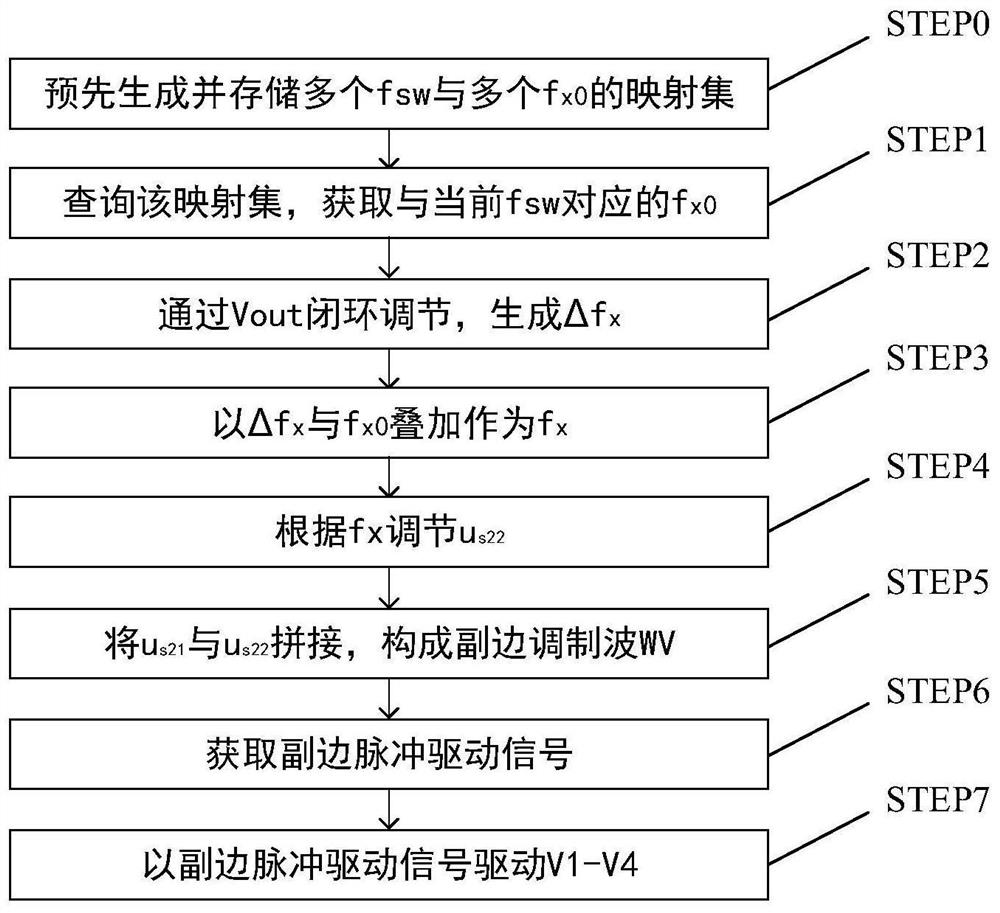
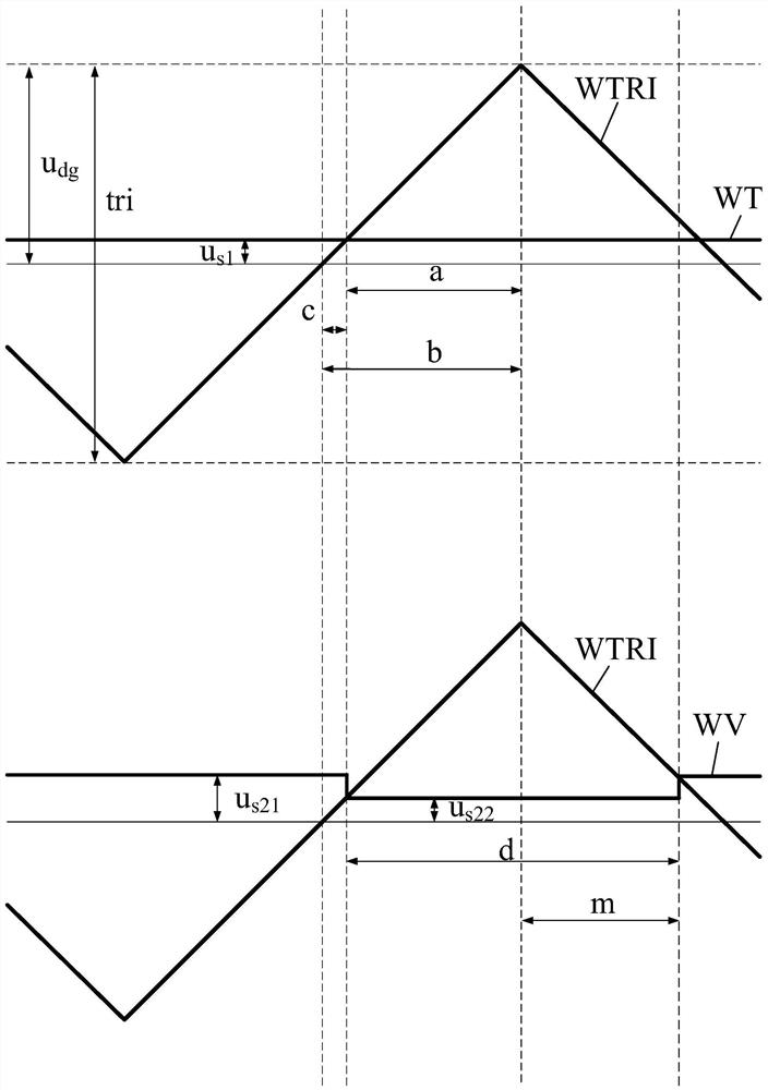

Image

  • Control method of LLC resonant converter
  • Control method of LLC resonant converter
  • Control method of LLC resonant converter

Examples


Embodiment Construction

[0028]The detailed features and advantages of the present invention are described in detail below in the specific embodiments, the content of which is sufficient to enable any person skilled in the art to understand the technical content of the present invention and implement it accordingly, and according to the specification, claims and drawings disclosed in this specification , those skilled in the art can easily understand the related objects and advantages of the present invention.

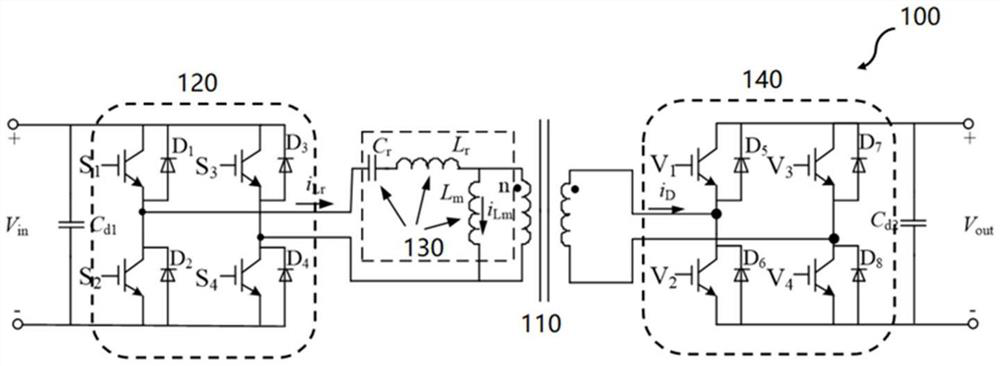
[0029] see figure 1 , the present invention is applied to the LLC resonant converter 100 , the LLC resonant converter 100 includes a transformer 110 , a primary bridge circuit 120 , an LLC resonant circuit 130 , and a secondary bridge circuit 140 . Transformer 110 has a primary side and a secondary side. The primary bridge circuit 120 and the LLC resonant circuit 130 are connected to the primary side of the transformer 110 , and the secondary bridge circuit 140 is connected to the secondary s...


PUM


Abstract

The invention provides a control method of an LLC resonant converter. A secondary side modulation wave is a square wave with a fixed voltage and an amplitude adjustment voltage in each period; and the amplitude adjustment voltage is adjusted according to the modulation frequency of the secondary side modulation wave, so that the switching devices of the secondary side bridge circuit are selectively and synchronously switched on and / or synchronously switched off with the switching devices of the primary side bridge circuit. By adjusting the alignment mode of the secondary pulse, the circuit gain under various working conditions can be finely adjusted, and it is ensured that the circuit gain does not change greatly under forward and reverse energy flow. The LLC resonant converter can be fixedly operated at the optimal switching frequency after being stably operated, so that the problem of overcurrent caused by saturation of a high-frequency transformer due to large-range frequency modulation is avoided.

Description

technical field [0001] The invention relates to the field of power electronics, in particular to a control method for an LLC resonant converter. Background technique [0002] In recent years, with the continuous development of high-frequency power electronics technology, research on new power conversion technologies in the fields of renewable energy, electric vehicles, and electric traction has received extensive attention. In the field of power grids, new concepts such as AC and DC hybrid transmission and distribution networks, DC transmission and distribution networks, DC microgrids, power electronic transformers, and energy routers are constantly being proposed. In many of the above research hotspots and applications, DC with bidirectional energy flow is required. The / DC converter acts as an interface between DC buses of different voltage levels. At the same time, in order to ensure the high efficiency and high power density of the DC converter, the DC / DC converter is a...

Claims


Application Information

Patent Timeline
IPC IPC(8): H02M3/335
CPCH02M3/3353Y02B70/10
Inventor 尚敬苏亮亮张志学漆宇陈涛罗文广彭赟黄超孙璐王跃
Owner CSR ZHUZHOU ELECTRIC LOCOMOTIVE RES INST
Learn More