


Quick Research
Generate reliable direction feasibility study reports for your R&D in just a few steps.

Technical Q&A
Discover and master advanced knowledge NOW. Basics, ideas, possibilities, all at once.

Find Solutions
As an expert in R&D theories, this can generate solutions to your technical problems instantly.

Evaluate Feasibility
Analyze your overall solution with one click, know your potential R&D risks in advance.

Monitor Landscape
Get weekly tech updates, stay abreast of the latest tech innovations and key insights.
System, device and method for testing service life of aero-engine blade
A technology of aero-engine and test system, applied in the direction of engine test, jet engine test, gas turbine engine test, etc., can solve the problems of complicated operation, long test time, affecting the service life of parts, etc.
- Summary
- Abstract
- Description
- Claims
- Application Information
AI Technical Summary
Problems solved by technology
Method used
Image

Examples
Embodiment 1
[0034] According to an embodiment of the present application, an aeroengine blade life testing system is provided, which is used for testing and confirming the blade life of the aeroengine blade.
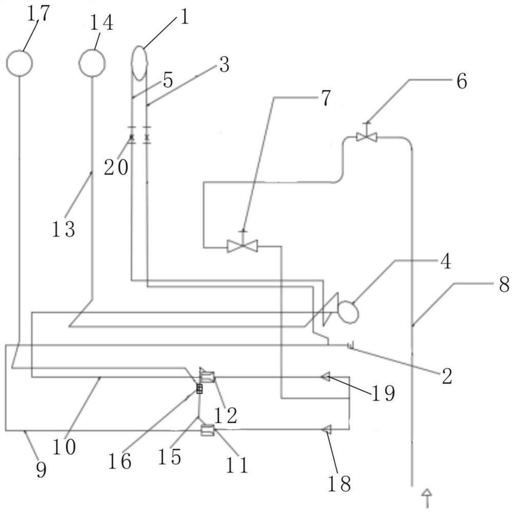
[0035] see figure 1 , the test system for the life of the aero-engine blade includes a reference standard pipeline, a test part pipeline, an air supply pipeline and a differential pressure gauge; among them, the air supply pipeline is used for the air supply of the entire system; the differential pressure gauge is used for measuring and testing The pressure difference between the air source standard pipeline and the test part pipeline.
[0036] In actual operation, the lasting life of the blades can be confirmed indirectly by comparing the pressure difference between the gas passing through the turbine disk and the reference standard pipeline, which can improve the efficiency of detection, stabilize the quality of the assembled turbine disk, and ensure the reliable operation of the ...
Embodiment 2
[0056] According to an embodiment of the present application, on the basis of the above-mentioned embodiments, an aero-engine blade life testing device is further provided, which includes the aero-engine blade life testing system involved in the above-mentioned embodiment.
[0057] In this embodiment, the specific installation structure of the test system for the blade life of the aeroengine is improved.
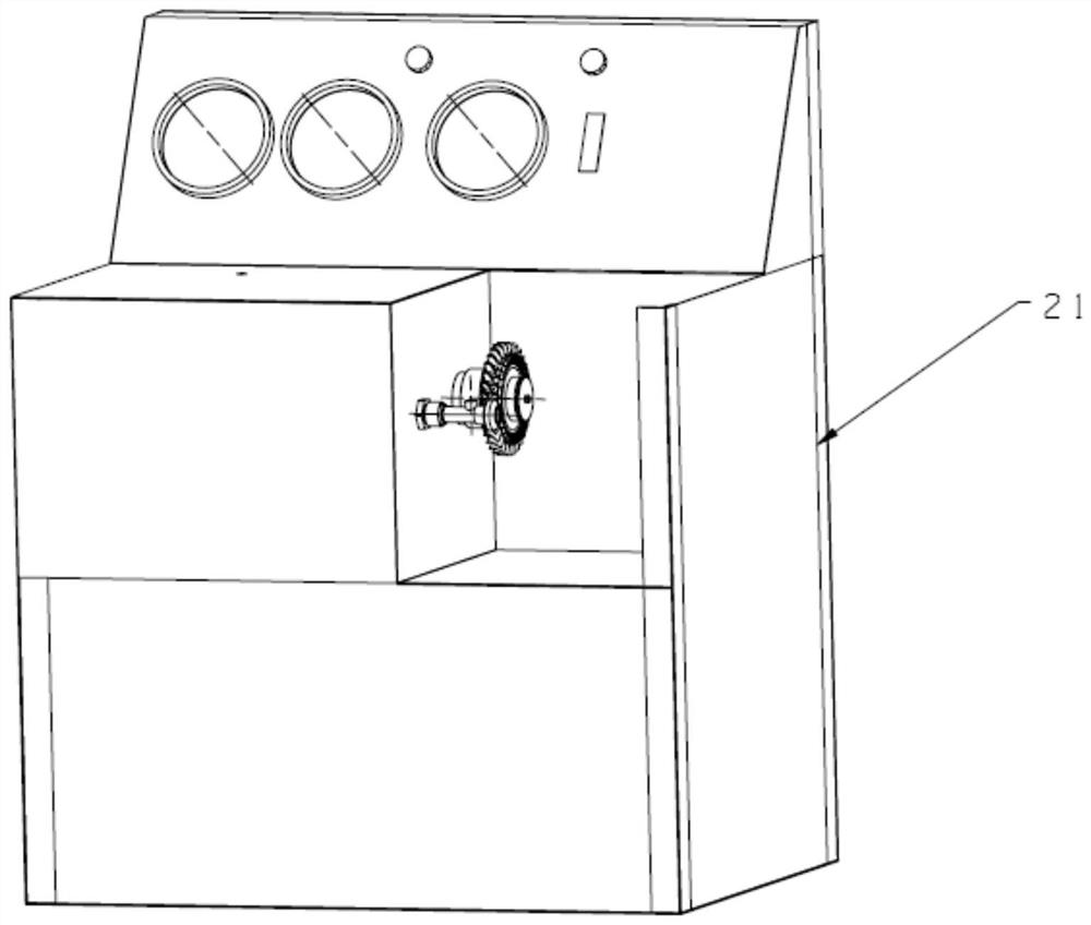
[0058] see Figure 2 ~ Figure 4 According to the invention, the test device for the life of the aero-engine blade includes an installation stand, on which the test system for the life of the aero-engine blade is installed.
[0059] The table top of the installation platform is a thin plate, which is specifically selected as a stainless steel sheet; the thin plate is fixed on the angle steel by screws to form the overall structure of the installation platform.
[0060] Mounting holes are opened on the thin plate, and correspondingly, instruments such as pressure gauge a, pre...
Embodiment 3
[0066] In the application of the present invention, a test method for the life of an aeroengine blade is also provided, based on the above-mentioned embodiments.
[0067] The specific method steps for the life test of aero-engine blades are as follows:
[0068] 1. Blockage of each blade cooling air intake of the turbine rotor assembly.
[0069] Plug each blade cooling air intake of the turbine rotor with a plug of rubber or equivalent material to prevent galling of the parts.
[0070] 2. Lubricate the test tool interface, and fasten the turbine rotor assembly to the test tool interface.
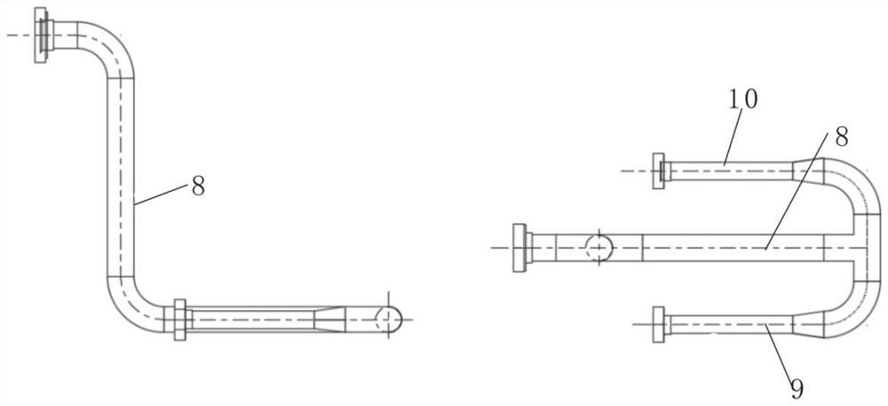
[0071] Among them, apply lubricating oil to the test tool interface of the aero-engine blade life test device. The lubricating oil can be MIL-PRF-7808 or other similar equivalent lubricating oil, and the turbine rotor assembly is placed on the test tool interface, see Figure 5 , so that the leading edge 22 of the blade faces to the left, that is, toward the upper direction of the test fixt...
PUM
| Property | Measurement | Unit |
|---|---|---|
| Diameter | aaaaa | aaaaa |
Abstract
Description
Claims
Application Information
 - R&D Engineer
- R&D Manager
- IP Professional
- Industry Leading Data Capabilities
- Powerful AI technology
- Patent DNA Extraction
Browse by: Latest US Patents, China's latest patents, Technical Efficacy Thesaurus, Application Domain, Technology Topic, Popular Technical Reports.
© 2024 PatSnap. All rights reserved.Legal|Privacy policy|Modern Slavery Act Transparency Statement|Sitemap|About US| Contact US: help@patsnap.com