Melt-blown yarn online plasma material surface modification device and method
An on-line and surface modification technology for melt-blown filaments, which is applied in the directions of melt-spinning, feeding solution to spinnerets, and filament forming processing. and filtering process
- Summary
- Abstract
- Description
- Claims
- Application Information
AI Technical Summary
Problems solved by technology
Method used
Image
Examples
Embodiment 1
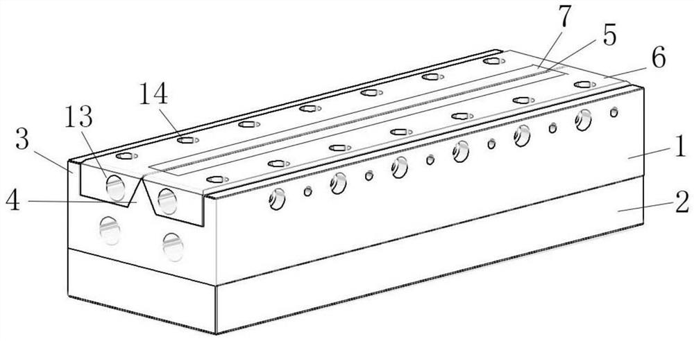
[0054] as attached figure 1 As shown, a melt-blown online plasma material surface modification device includes a spinneret 1, the bottom of the spinneret 1 is connected to a feed plate 2, and the upper end of the spinneret 1 is provided with a side end protrusion 3 and the middle raised portion 4, an airflow plate 6 is arranged between the middle raised portion 4 and the side end raised portion 3, and a plasma discharge structure 7 is arranged at the contact between the airflow plate 6 and the middle raised portion 4.
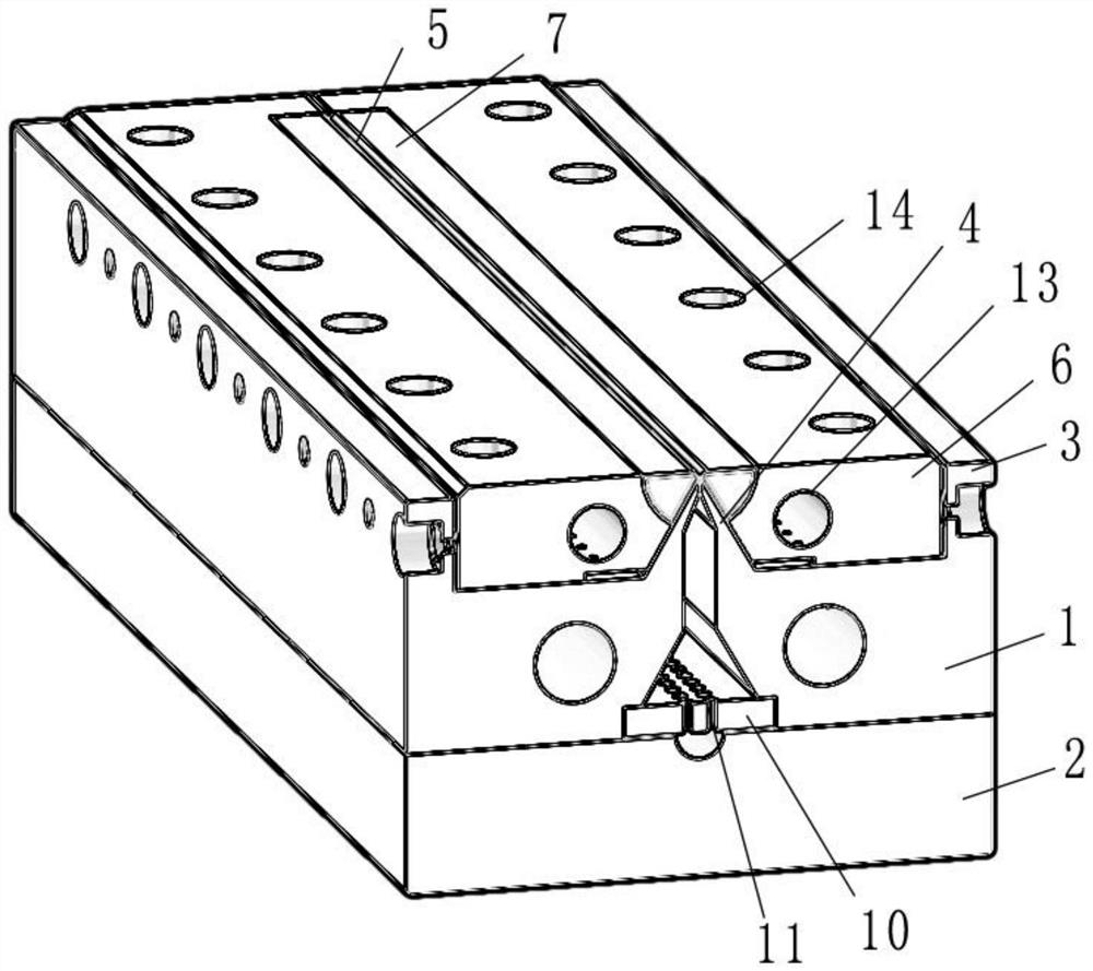
[0055] Further, as attached figure 2 As shown, the inside of the spinneret is provided with a hollow structure, and the hollow structure is used to transmit air flow and melt material; the cross-section of the air flow plate 6 is a right-angled trapezoid, and the upper bottom of the right-angled trapezoid is in contact with the upper end surface of the spinneret 1. connected.
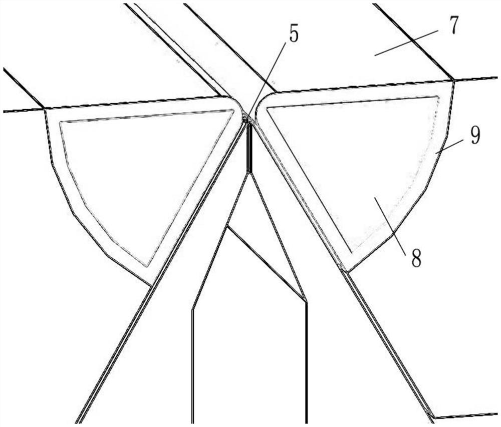
[0056] Further, as attached Figure 4 As shown, the plasma discharge structure 7...
Embodiment 2
[0067] This embodiment is described on the basis of the above-mentioned embodiment 1, and the similarities with the above-mentioned embodiment 1 will not be repeated.
[0068] This embodiment mainly introduces a plasma discharge structure.
[0069] A plasma discharge structure is embedded in the gas flow plate 6 , and the length of the plasma discharge structure is smaller than the length of the gas flow plate 6 .
[0070] Further, the plasma discharge structure 7 is a cylinder, the outermost layer of the plasma discharge structure is an insulating layer, and n electrodes are arranged inside the insulating layer, and springs are arranged between the n electrodes, and the springs The n electrodes are closely matched with the ceramic insulator 10 to ensure sufficient contact between the electrodes and the ceramic.
[0071] Further, one end of the electrode is connected to an external high-voltage power supply device.
[0072] Further, the upper end of the plasma discharge stru...
Embodiment 3
[0077] This embodiment is described on the basis of the above-mentioned embodiment 1, and the similarities with the above-mentioned embodiment 1 will not be repeated.
[0078] This embodiment mainly introduces a method for surface modification of a melt-blown online plasma material. Using the described melt-blown online plasma material surface modification device includes the following steps:
[0079] S1, device assembly and power on;
[0080] S2, the plasma discharge structure 7 generates a large amount of plasma between the gas outlets 5;
[0081] S3, passing the melted chemical fiber raw material into the melt channel 15 of the feed plate 2;
[0082] S4. After the molten chemical fiber raw material is filtered by the filter layer 10, the filamentous material is ejected from the air outlet 5 of the spinneret 1;
[0083] S5. The plasma modifies the surface of the ejected filamentary material;
[0084] S6, feed gas into the air inlet 13;
[0085] S7, the gas moves to the a...
PUM
 Abstract
Description
Claims
Application Information
 - Generate Ideas
- Intellectual Property
- Life Sciences
- Materials
- Tech Scout
- Unparalleled Data Quality
- Higher Quality Content
- 60% Fewer Hallucinations
Browse by: Latest US Patents, China's latest patents, Technical Efficacy Thesaurus, Application Domain, Technology Topic, Popular Technical Reports.
© 2025 PatSnap. All rights reserved.Legal|Privacy policy|Modern Slavery Act Transparency Statement|Sitemap|About US| Contact US: help@patsnap.com


