
Biconical antenna unit structure

A biconical antenna and unit structure technology, which is applied to the connection of the antenna grounding switch structure, the structural form of the radiating element, the antenna, etc., can solve the problems of the complex shape of the radiating arm, the difficulty of processing, and the easy deformation of the antenna unit structure, and achieve a simple structure. , The effect of reducing processing difficulty and easy processing

Inactive Publication Date: 2021-04-27
BEIJING INST OF RADIO MEASUREMENT
View PDF5 Cites 0 Cited by
  • Summary
  • Abstract
  • Description
  • Claims
  • Application Information

AI Technical Summary

Problems solved by technology

[0003] In order to solve the above problems, the present invention provides a biconical antenna unit structure to reduce the quality of the biconical antenna unit and solve the problem that the antenna unit structure is easily deformed due to the large mass of the radiation arm in the prior art, and the Difficulty in processing due to the complex shape of the arm

Method used


Image

  • Biconical antenna unit structure
  • Biconical antenna unit structure
  • Biconical antenna unit structure

Examples


Embodiment Construction

[0028] In order to illustrate the present invention more clearly, the present invention will be further described below with reference to the preferred embodiments and accompanying drawings. Similar parts in the figures are denoted by the same reference numerals. It should be understood by those skilled in the art that the content specifically described below is illustrative rather than restrictive, and should not limit the protection scope of the present invention.

[0029] In the description of this application, it should be noted that the orientation or positional relationship indicated by the terms "upper", "lower", etc. is based on the orientation or positional relationship shown in the accompanying drawings, and is only for the convenience of describing the application and simplifying the description, Rather than indicating or implying that the referred device or element must have a particular orientation, be constructed and operate in a particular orientation, it should...


PUM


Abstract

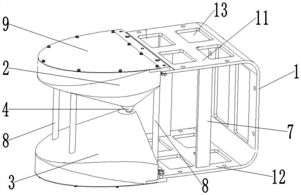
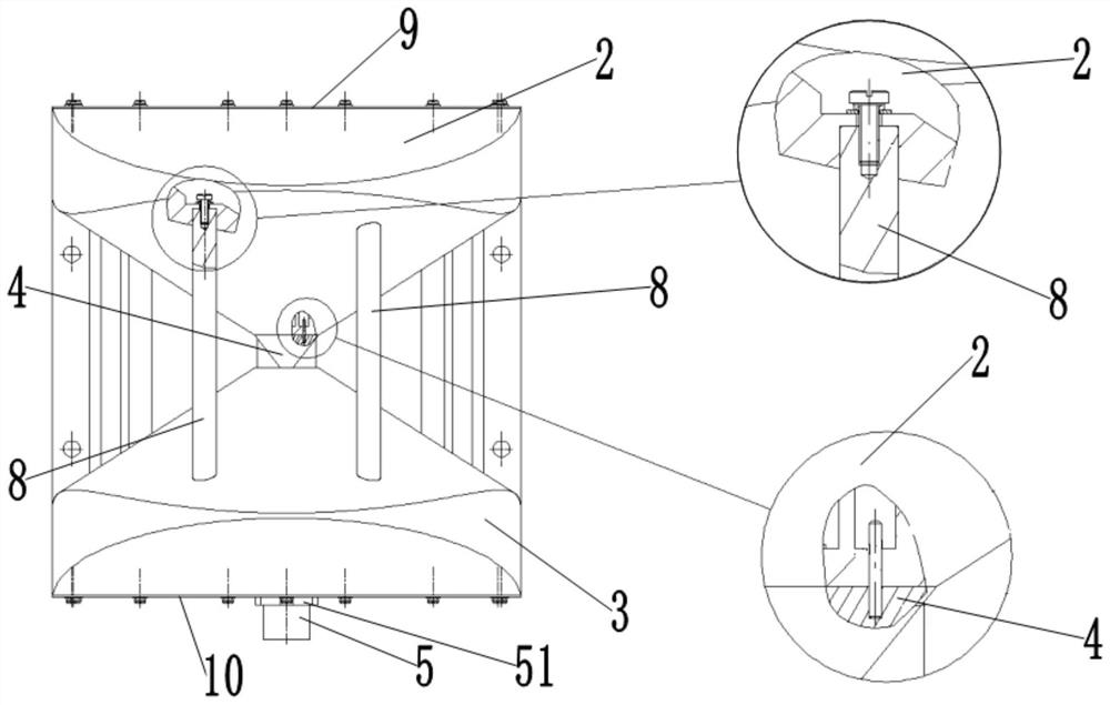
The embodiment of the invention discloses a biconical antenna unit structure. The biconical antenna unit structure comprises a U-shaped bracket; an upper radiation arm which is combined and fixed on the edge of the side wall of the U-shaped bracket; a lower radiation arm which is combined and fixed on the edge of the other side wall of the U-shaped bracket and is arranged corresponding to the upper radiation arm, wherein both the upper radiation arm and the lower radiation arm are conical, and the upper radiation arm and the lower radiation arm are symmetrically arranged; a feed needle seat which is positioned between the upper radiation arm and the lower radiation arm and is combined and fixed at the conical tip of the upper radiation arm; a radio frequency coaxial connector which is combined and fixed on one side, far away from the upper radiation arm, of the lower radiation arm; and a pin rod which penetrates through the lower radiation arm and is communicated with the feed pin seat and the radio frequency coaxial connector. Through weight reduction processing of the support, the upper radiation arm and the lower radiation arm and use of the supporting columns and the supporting plates, the structural rigidity of the antenna unit structure is effectively improved, and the antenna unit structure has the advantages of being simple in structure, good in rigidity, easy to machine and the like.

Description

technical field [0001] The invention relates to the field of radar antenna structures. More specifically, it relates to a biconical antenna unit structure. Background technique [0002] The biconical antenna unit is used to radiate high-power microwaves, and has high requirements for dimensional accuracy. The existing technology is to make the two radiating arms of an antenna unit and the antenna bracket into a whole. The size of the cantilever is long, so the structure of the antenna unit is easily deformed, which affects the electrical performance, and the radiation surfaces of the two radiating arms of the antenna unit have complex shapes, which are difficult to process, and it is difficult to ensure the processing quality. SUMMARY OF THE INVENTION [0003] In order to solve the above problems, the present invention provides a biconical antenna unit structure, so as to reduce the quality of the biconical antenna unit, solve the problem that the antenna unit structure i...

Claims


Application Information

Patent Timeline
Patent Type & Authority Applications(China)
IPC IPC(8): H01Q1/36H01Q1/50H01Q1/12
CPCH01Q1/36H01Q1/50H01Q1/1207
Inventor 郑东豪陈章平李庆王志杰李鹏刚
Owner BEIJING INST OF RADIO MEASUREMENT
Learn More