Current limiting structure and circuit breaker

A circuit breaker and main circuit technology, which is applied to the operation/release mechanism of the protection switch, adjusting the conditions of the protection switch, etc. simple structure

Pending Publication Date: 2021-04-27
ZHEJIANG TENGEN ELECTRIC
View PDF0 Cites 1 Cited by
  • Summary
  • Abstract
  • Description
  • Claims
  • Application Information

AI Technical Summary

Problems solved by technology

[0005] The technical problem to be solved by the present invention is to overcome the fact that the circuit breaker in the prior art increases the current-limiting resistance and adopts a fixed resistance with a small resistance, which is not conducive to arc extinguishing. It is a big technical problem, so as to provide a current limiting structure that is beneficial to arc extinguishing without enlarging the arc extinguishing chamber and a circuit breaker with the current limiting structure

Method used


Image

  • Current limiting structure and circuit breaker
  • Current limiting structure and circuit breaker
  • Current limiting structure and circuit breaker

Examples


Embodiment 1

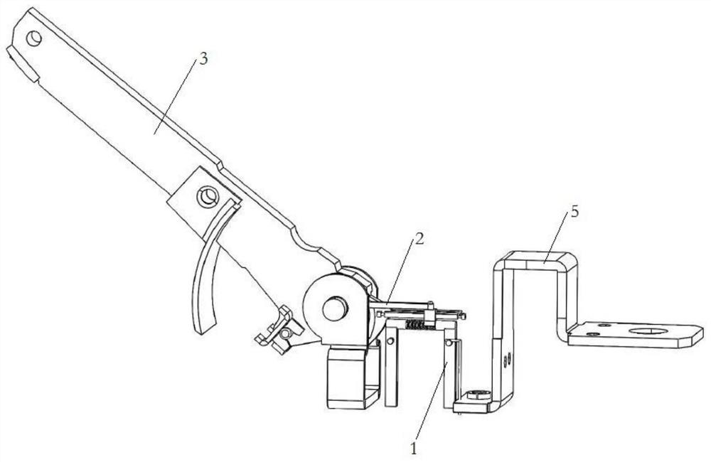
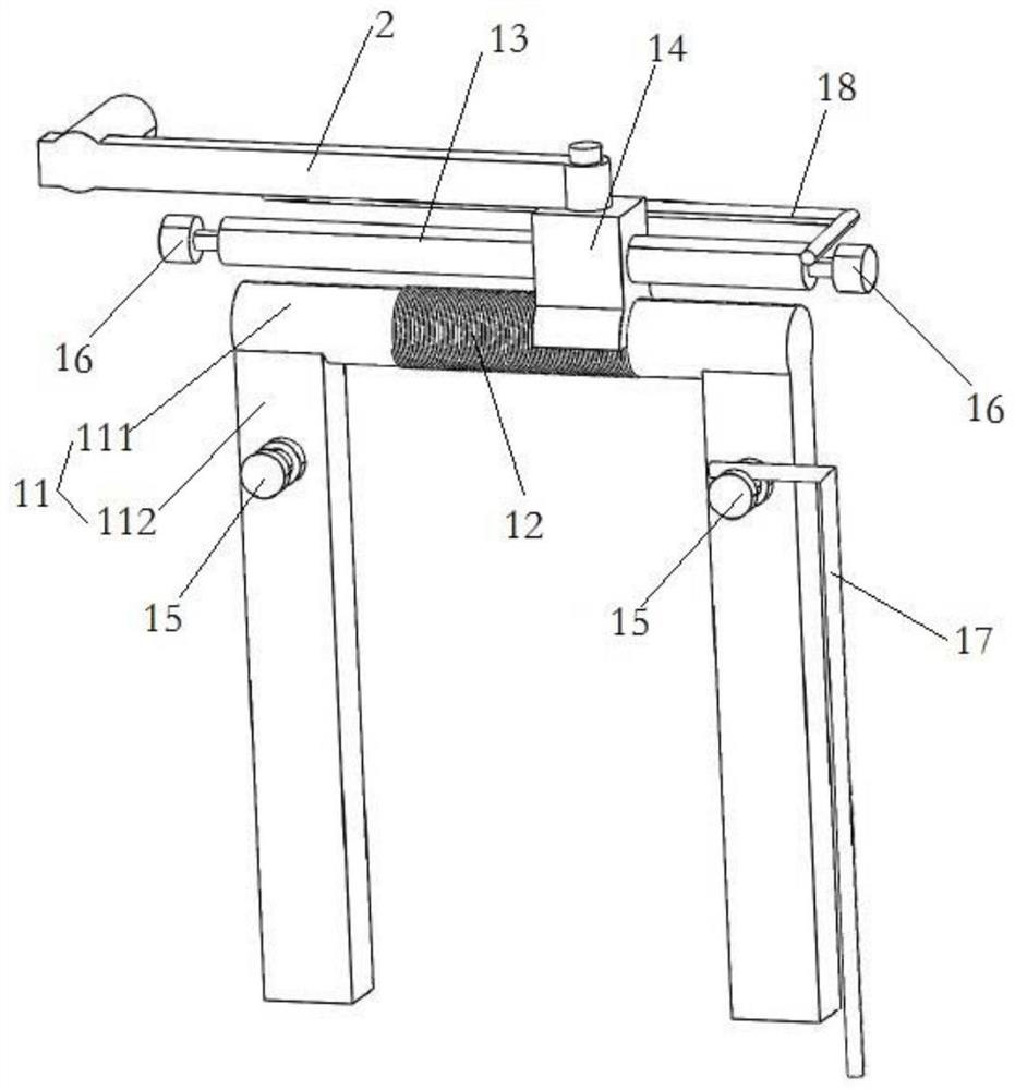
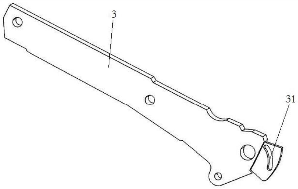
[0064] For the current limiting structure of this embodiment, see Figure 1 to Figure 5 As shown, it includes a variable resistance assembly 1 and a linkage mechanism 2 . One end of the variable resistance assembly 1 is suitable for electrical connection with the heating element 5 in the circuit breaker, and the other end is electrically connected with the moving contact 3 in the circuit breaker to be connected in series in the main circuit of the circuit breaker. One end of the linkage mechanism 2 is linked to the variable resistor assembly 1 , and the other end is linked to the moving contact 3 . The variable resistance assembly 1 has a first state in which the resistance value tends to be zero when the moving contact 3 is connected to the static contact 4 in the circuit breaker, and when the main circuit current is too large, the driven contact 3 and the static contact The driving force of the contact 4 is repulsed and the resistance value increases to the second state. I...

Embodiment 2

[0073] The circuit breaker of this embodiment, such as Figure 1 to Figure 8 As shown, it includes the housing 7, the contact assembly installed in the housing 7, the operating mechanism 6 installed on the housing 7 for driving the contact assembly to close / open, and the current limiting structure in Embodiment 1. . The contact assembly is arranged in the housing 7 and includes a moving contact 3 and a static contact 4 . The operating mechanism 6 is linked with the movable contact 3 through a linkage assembly. The current limiting structure is installed in the installation cavity of the housing 7 for installing the contact assembly, and is linked to the movable contact 3 of the contact assembly through the linkage mechanism 2 . Since the above-mentioned current limiting structure is adopted, at least the advantages of the current limiting structure of the above-mentioned embodiment 1 are obtained, and details will not be repeated here. At the same time, due to the current-l...


PUM


Abstract

The invention relates to the technical field of circuit breakers and particularly relates to a current-limiting structure and a circuit breaker. The current-limiting structure comprises a variable resistor assembly, wherein one end of the variable resistor assembly is suitable for being electrically connected with a heating element in the circuit breaker, and the other end of the variable resistor assembly is electrically connected with a moving contact in the circuit breaker to be connected in series in a main loop of the circuit breaker; one end of the linkage mechanism is in linkage connection with the variable resistor assembly, and the other end is in linkage connection with the moving contact; the variable resistor assembly has a first state in which the resistance value tends to zero when the moving contact is connected with a static contact in the circuit breaker, and a second state in which the resistance value is increased under the repulsion driving force of the moving contact and the static contact when the current of the main loop is too large; in the first state, the variable resistor assembly does not limit the current of the main loop; in the second state, the linkage mechanism and the moving contact are linked to provide driving force, and the variable resistor assembly limits the current of the main loop. The arc voltage is improved, and arc extinguishing is facilitated. The structure is advantaged in that the arc extinguishing capability is improved without increasing the size and the opening distance of the arc extinguishing chamber, and the size of the product is reduced.

Description

technical field [0001] The invention belongs to the technical field of circuit breakers, and in particular relates to a current limiting structure and a circuit breaker. Background technique [0002] A circuit breaker is a switching device that can carry and break current under abnormal circuit conditions within a specified time. Inside the circuit breaker, there are moving contacts and static contacts that can perform on-off operations. The moving contacts Driven by the operating mechanism. [0003] The operating mechanism of the circuit breaker is operated by the button extending out of the casing, and the moving contact and the static contact in the circuit breaker are driven to contact or disconnect through multi-stage linkage. When the moving contact and the static contact are in contact, the The load connected to the circuit breaker supplies power. [0004] In order to achieve the breaking index, reduce the actual current when breaking, and protect the internal compo...

Claims


Application Information

Patent Timeline
Patent Type & Authority Applications(China)
IPC IPC(8): H01H71/74H01H71/10
CPCH01H71/10H01H71/74
Inventor 袁辉高腾飞吴燕平高柏勇臧卫令狐绍江
Owner ZHEJIANG TENGEN ELECTRIC
Why Eureka
Try Eureka