Insulator assembly and high-voltage switch equipment using insulator assembly

A technology of insulators and components, which is applied in the field of insulator components and high-voltage switchgear, and can solve problems such as unstable induced voltage signals

Active Publication Date: 2021-04-27
PINGGAO GRP +2
View PDF16 Cites 1 Cited by
  • Summary
  • Abstract
  • Description
  • Claims
  • Application Information

AI Technical Summary

Problems solved by technology

[0007] The purpose of the present invention is to provide an insulator assembly to solve the technical problem in the prior art that there is clutter capacitance between the electrode and the main conductor, which causes the induced voltage signal to be unstable; it also provides a high-voltage switchgear using the insulator assembly

Method used


Image

  • Insulator assembly and high-voltage switch equipment using insulator assembly
  • Insulator assembly and high-voltage switch equipment using insulator assembly
  • Insulator assembly and high-voltage switch equipment using insulator assembly

Examples


specific Embodiment 1

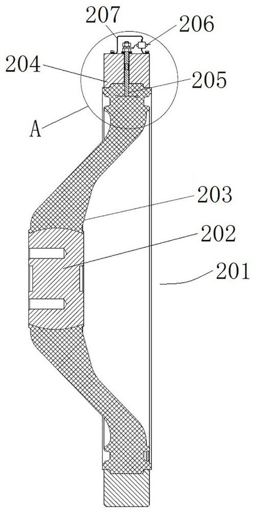
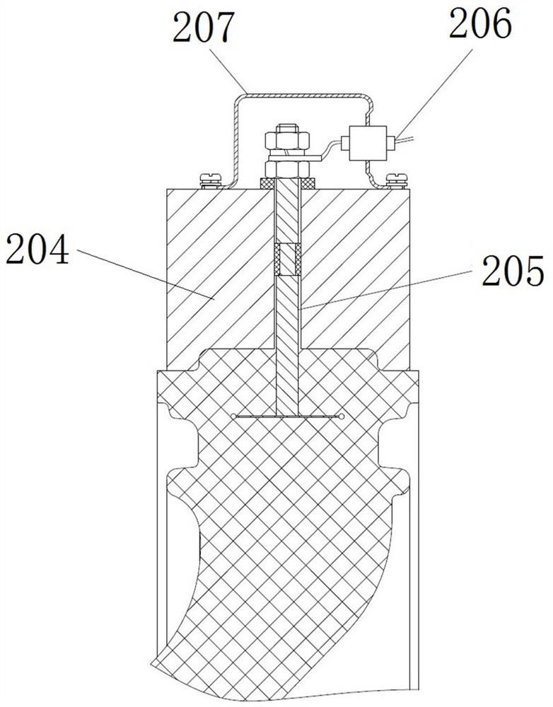
[0066]Such asFigure 4 to 6As shown, the insulator assembly includes an insulator 301, a sensor, a T-shaped joint 314, and a charging display device 316. The insulator 301 in the present embodiment is a basin insulator, including the intermediate main conductor 302, the edge metal flange 303, and the main conductor The insulating portion 304 between 302 and the metal flange 303 is formed, and the basin insulator is formed in a manner.

[0067]An electrode mounting hole is opened on the outer peripheral surface of the metal flange 303, and the electrode mounting hole extends along the radial direction of the insulator 301, and the electrode mounting hole extends into the insulating portion 304, the electrode mounting hole is used to mount the sensor, the hole of the electrode mounting hole. For sphere. The electrode mounting holes here include two parts, and a portion is located in the insulating portion 304, and the other portion is opened in the metal flange 303, wherein the portion lo...

Embodiment 1

[0077]In Example 1, there was a pin on the T-shaped joint, and the wiring portion on the electrode was an elastic jug. In the present embodiment, the wiring portion on the electrode is a pin, and an elastic jug on the T-shaped joint is also achieved, and the T-shaped joint is connected to the electrode.

[0078]When actually designed and processed, the shape of the joint can be changed.

[0079]Alternatively, the wiring portion on the electrode is a threaded hole opened on the electrode, and the outer shield cable is secured to the electrode by a DT joint.

specific Embodiment 3

[0081]In Example 1, between the cover plate and the metal flange, there was a seal between the electrodes and the electrode mounting hole wall. In this embodiment, only one seal is provided.


PUM


Abstract

The invention belongs to the technical field of high-voltage switches, and particularly relates to an insulator assembly and high-voltage switch equipment using the same. The insulator assembly comprises an insulator and a sensor; the insulator comprises a main conductor, a metal flange and an insulating part, and an electrode mounting hole extending into the insulating part is formed in the peripheral surface of the metal flange; the sensor comprises an electrode penetrating through the electrode mounting hole, the electrode is used for sensing a voltage signal of the main conductor, and the electrode is provided with a wiring part used for being connected with an electrified display device; the electrode is provided with an electrode inner end facing the main conductor, the electrode inner end can be fitted with the hole bottom of the electrode mounting hole, and the electrode inner end is used for being matched with the main conductor to form a detection capacitor; the insulator assembly further comprises a cover plate and an elastic assembly, and the cover plate is fixedly installed on the metal flange and used for jacking the electrodes in the direction where the main conductor is located; and the elastic piece is arranged in the electrode and/or between the electrode and the cover plate so as to press the inner end of the electrode against the bottom of the electrode mounting hole.

Description

Technical field[0001]The present invention belongs to the technical field of high pressure switch, and more particularly to an insulator assembly and a high pressure switching device using the insulator assembly.Background technique[0002]In the prior art, in order to accurately reactively reactivate the power circuit of the high-pressure switching device, the charge detecting device is used to detect, and the high pressure switching apparatus includes a housing and a central conductor disposed within the housing, and the adjacent housing is relying on an insulator. The central conductor in the adjacent housing is also fixed, and the conductive communication is achieved through the main conductor in the insulator. The current high-voltage switching device charging detecting device is set to the structure of the high voltage switching device, mainly two Design structure.[0003]The first structure is likefigure 1 As shown, a particular size is provided on the housing 102, which is close...

Claims


Application Information

Patent Timeline
Patent Type & Authority Applications(China)
IPC IPC(8): H01B17/00H01B17/38H01H9/02
CPCH01B17/005H01B17/38H01H9/0271
Inventor 李俊锋乔超伟王祯姚明明江经华张银穗孙清超张超军贺永明丁伯睿
Owner PINGGAO GRP
Why Eureka
Try Eureka