A shell and tube heat exchanger

A technology of shell-and-tube heat exchangers and heat exchange tubes, which is applied in the direction of indirect heat exchangers, heat exchanger types, heat transfer modification, etc., and can solve the problems of supporting baffle flow dead angle, low shell side heat transfer coefficient, etc. Problems such as large fluid resistance, to achieve the effect of eliminating flow dead angle, increasing heat transfer coefficient, and reducing impact

Active Publication Date: 2022-07-15
FOSHAN UNIVERSITY
View PDF9 Cites 0 Cited by
  • Summary
  • Abstract
  • Description
  • Claims
  • Application Information

AI Technical Summary

Problems solved by technology

[0002] Existing shell-and-tube heat exchangers generally set baffles in the shell side to support and strengthen the heat exchange tubes. Traditional shell-and-tube heat exchangers generally use bow-shaped baffles, which are shell-and-tube heat exchangers. For the parts that support the heat exchange tubes, the existing support baffles are prone to flow dead angles, and the heat transfer area cannot be fully utilized, so there are problems of low heat transfer coefficient of the shell side, easy scaling, and large fluid resistance; And when the fluid flows laterally through the tube bundle, it may also cause the tube to generate induced vibration, which will damage the reliability of the tube and its connection with the tube sheet; in addition, the existing shell-and-tube heat exchanger generally adopts Internal inserts to strengthen heat transfer tubes, such as inserting ties, helical sheets, spiral coils and other heat exchange tubes in the tubes, while increasing the heat transfer coefficient in the tubes, the flow resistance in the tubes also increases, and more power needs to be provided; not applicable Heat transfer of low Reynolds number or high viscosity fluids; easy to scale, heat transfer efficiency gradually decreases with time during use

Method used


Image

  • A shell and tube heat exchanger
  • A shell and tube heat exchanger
  • A shell and tube heat exchanger

Examples


Embodiment Construction

[0026] This part will describe the specific embodiments of the present invention in detail, and the preferred embodiments of the present invention are shown in the accompanying drawings. Each technical feature and overall technical solution of the invention should not be construed as limiting the protection scope of the invention.

[0027] In the description of the present invention, it should be understood that the azimuth description, such as the azimuth or position relationship indicated by up, down, front, rear, left, right, etc., is based on the azimuth or position relationship shown in the drawings, only In order to facilitate the description of the present invention and simplify the description, it is not indicated or implied that the indicated device or element must have a particular orientation, be constructed and operated in a particular orientation, and therefore should not be construed as limiting the present invention.

[0028] In the description of the present in...


PUM


Abstract

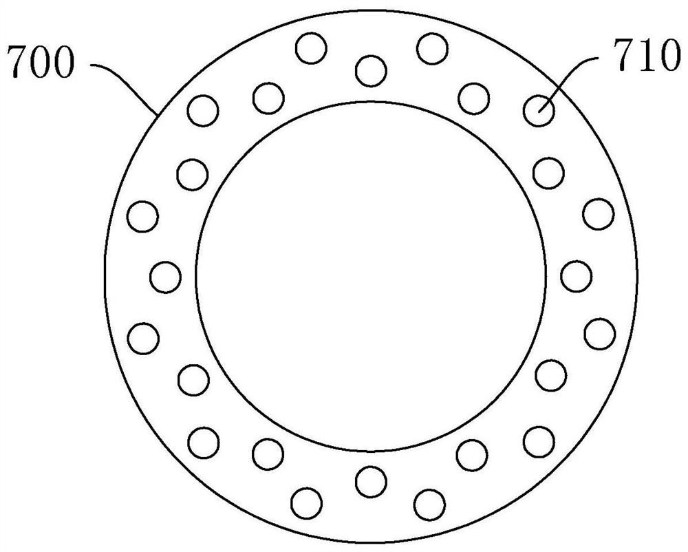
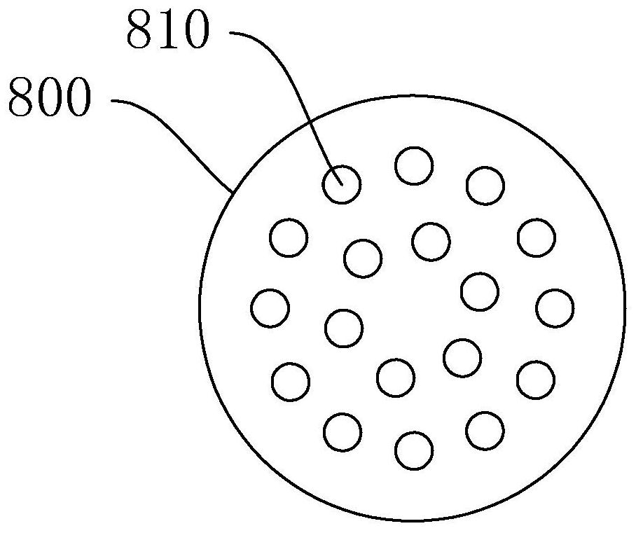
The invention discloses a shell-and-tube heat exchanger, which comprises a shell, a front head, a rear head, a heat exchange tube, a tube bundle support, a front tube plate, a rear tube plate, a tube side inlet, a tube side outlet, The shell side inlet, the shell side outlet and the tie rod, the heat exchange tube includes a tube body and an inner ball piece, and the inner ball piece includes metal balls arranged in the tube body at equal intervals along the axis of the tube body, connected to each adjacent two The metal rod between the metal spheres, the tube bundle support is to dig a circle from the middle part of a full circular plate, and the area of ​​the dug out circle is equal to the area of ​​the remaining ring, and the remaining ring is the baffle A , the baffle A is provided with a tube hole a for the heat exchange tube to pass through, and the dug out circle is the baffle B, and the baffle B is provided with a tube hole b for the heat exchange tube to pass through. The flow plate B is fixedly connected to the front tube plate and the rear tube plate through a plurality of tie rods. Compared with the existing enhanced heat transfer technology, the tube-side and shell-side convection heat transfer coefficients are increased, while the resistance increase is very small.

Description

technical field [0001] The invention relates to the field of heat exchangers, in particular to a shell-and-tube heat exchanger. Background technique [0002] Existing shell-and-tube heat exchangers generally set baffles in the shell side to support and reinforce the heat exchange tubes. Traditional shell-and-tube heat exchangers generally use arcuate baffles, which are shell-and-tube heat exchangers. Among the components that support the heat exchange tube, the existing supporting baffles are prone to flow dead corners, and the heat transfer area cannot be fully utilized, resulting in the problems of low shell-side heat transfer coefficient, easy scaling, and large fluid resistance; Moreover, when the fluid flows laterally through the tube bundle, the tube may also induce vibration, which will destroy the reliability of the tube and its connection with the tube sheet. The inner insert strengthens the heat transfer tube, such as inserting a heat transfer tube such as a tie, ...

Claims


Application Information

Patent Timeline
Patent Type & Authority Patents(China)
IPC IPC(8): F28D7/16F28F13/00
CPCF28D7/16F28F13/06
Inventor 黄德斌陈沁阳陈欣然梁颖欣朱远航
Owner FOSHAN UNIVERSITY
Why Eureka
Try Eureka