
Method for Preventing Metal Materials from Scratching Tube Wall in Tube Annealing Furnace

A technology of metal materials and annealing furnaces, which is applied in the direction of metal processing equipment, furnaces, furnace types, etc., can solve the problem of the same force on the outer surface of the metal strip body, and achieve the effects of reducing bending deformation, reducing residual stress, and reducing burrs

Active Publication Date: 2021-08-24
广州众山精密科技有限公司
View PDF0 Cites 0 Cited by
  • Summary
  • Abstract
  • Description
  • Claims
  • Application Information

AI Technical Summary

Problems solved by technology

[0005] The metal bar body is a long material, which is annealed as a whole, and can be rotated independently through the set rotating tube, driving the second connecting tube to slide in the front and rear directions inside the chute three, and can be bent according to the actual situation of the metal bar body. Targeted alignment of the area, the alignment here refers to the alignment process in the horizontal direction, and it is convenient to replace and maintain a single rotating tube, through the first driving motor, the third rotating rod, the The two rotating rods and the second tension wheel are used in conjunction to make the metal strip body move towards the direction close to the metal strip guide box, and the normal operation of the tension mechanism as a whole can be realized through a first driving motor, avoiding the occurrence of multiple motor installations It is not convenient to maintain the same force on the outer surface of the metal strip body;

Method used


Image

  • Method for Preventing Metal Materials from Scratching Tube Wall in Tube Annealing Furnace
  • Method for Preventing Metal Materials from Scratching Tube Wall in Tube Annealing Furnace
  • Method for Preventing Metal Materials from Scratching Tube Wall in Tube Annealing Furnace

Examples


Embodiment 1

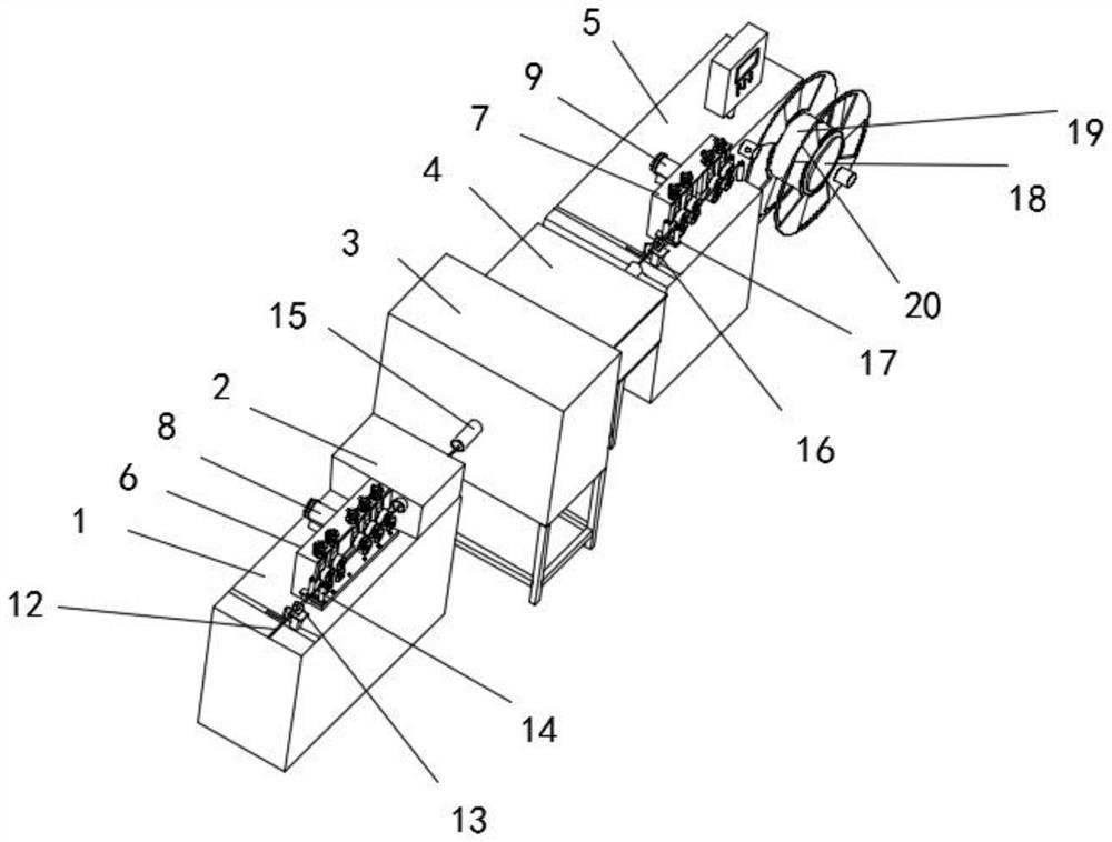
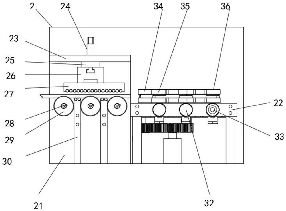
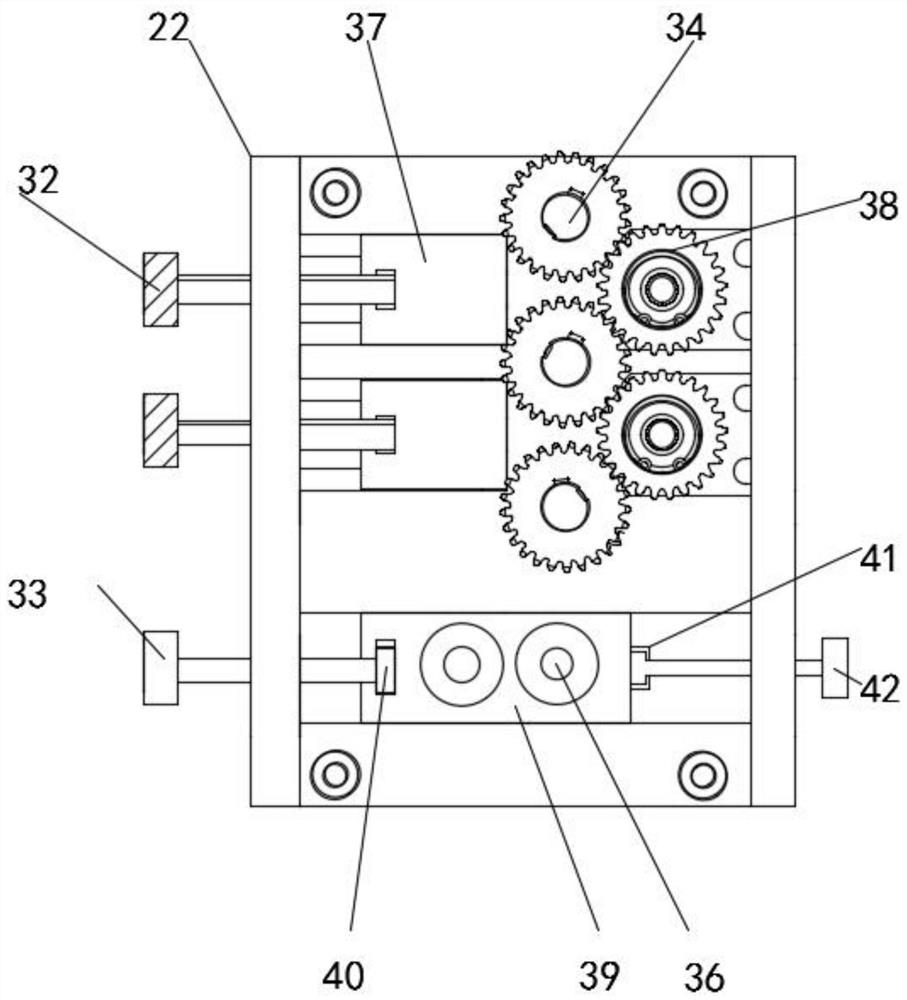
[0034] Such as Figure 1-5 As shown, the method for preventing metal material from scratching the tube wall in the tube annealing furnace comprises the following steps:

[0035] Step 1: Take a roll of strip-shaped metal material, which is the metal strip body 12;

[0036] Step 2: Pass the metal bar body 12 through the inside of the first ring encoder 13 into the annealing device, and control the first ring encoder 13 to slide on the upper surface of the first support base 1 through the bar-shaped groove 1, so that the metal bar body 12 Pass through the first limit stop post 14 to the position between the first tension wheel 66 and the second tension wheel 68, start the first drive motor 8, and drive the third rotating rod 70 to rotate, the outer surface of the third rotating rod 70 The socketed gear four is engaged with the gear three socketed on the outer surface of the second rotating rod 67 near the rear end, thereby driving the second rotating rod 67 to rotate, and then d...


PUM


Abstract

The invention discloses a method for preventing metal materials from being scratched in a tubular annealing furnace, comprising the following steps: Step 1: take a roll of long strip-shaped metal material, which is a metal strip body; 1. The rotating column, the first rotating drum, the first connecting column, the second connecting column, the third connecting column, the first fixing column, the grinding rotating column 1 and the grinding rotating column 2 are used together to reduce the burrs on the metal strip body. Avoid the up and down jump of the metal strip body; rotating the second rotating disc can realize the up and down movement of the second connecting plate, and adjust the metal strip body to bend upward, which can effectively reduce the bending deformation of the material in the furnace tube, so as to achieve Reduce the chance of scratches on the surface of the material. Rotating the third rotating disc can realize the left and right movement of the second connecting plate, and adjust the position of the metal strip body into the furnace tube according to the position of the scratch. The problem of scratches occurs due to size limitations.

Description

technical field [0001] The invention relates to the technical field of metal materials, in particular to a method for preventing metal materials from being scratched on tube walls in a tube annealing furnace. Background technique [0002] At present, the metal processing market (CNC processing, etc.) has an increasing demand for metal profiles in order to improve processing efficiency, save costs, and reduce losses. ) requirements are getting higher and higher, which puts forward higher requirements for the control of metal materials in the process of processing. Annealing is an indispensable link. The quality of annealing is related to the surface quality, hardness stability and profile of stainless steel profiles The size of the residual stress. [0003] Normal tubular annealing generally consists of a feeding part, a cleaning part, an annealing furnace heating part, an annealing furnace cooling part, and a material receiving part. The furnace tubes in the annealing furna...

Claims


Application Information

Patent Timeline
Patent Type & Authority Patents(China)
IPC IPC(8): C21D1/26C21D9/573B24B9/04B24B41/00B24B41/02B24B47/12B21D3/05
CPCB21D3/05B24B9/002B24B9/04B24B41/005B24B41/02B24B47/12C21D1/26C21D9/0025C21D9/0062C21D9/5732
Inventor 朱华明刘孝东邱树生周毅军郑玉坤贺霞肖林平
Owner 广州众山精密科技有限公司
Learn More