
UTG glass ceramic plate tempered frame

A glass-ceramic and ceramic technology, applied in the field of UTG glass-ceramic plate tempering frame, can solve problems such as edge chipping, touch screen glass fragments, falling into the tempering furnace, etc., to reduce surface pits and avoid mutual contact.

Pending Publication Date: 2021-04-27
安徽金龙浩光电科技有限公司
View PDF4 Cites 1 Cited by
  • Summary
  • Abstract
  • Description
  • Claims
  • Application Information

AI Technical Summary

Problems solved by technology

[0003] At present, during the operation process and subsequent cleaning process of the existing tempered frame, due to the thermal expansion of the glass sheet and the fixing rod under high temperature conditions, the touch screen glass fragments, chipped edges, and sequins often appear. Due to the thermal expansion of the sheet and the fixing rod, the glass substrate cannot be completely impregnated with the strengthening solution. It needs to be inverted, re-inserted and cleaned for the chemically tempered glass. It is also easy to scratch during the process, which affects the production efficiency and yield of glass strengthening.
In order to ensure that the glass lens is not polluted, corroded and scratched during tempering, transportation, storage and use, to protect the original smooth and shiny surface, and to reduce debris, during the processing of UTG glass tempering, the ultra-thin UTG glass cannot Use conventional methods to fix, and the process is likely to cause a large number of problems such as fragmentation, chipping, falling into the tempering furnace, etc., which cannot meet the requirements of mass production

Method used


Image

  • UTG glass ceramic plate tempered frame
  • UTG glass ceramic plate tempered frame
  • UTG glass ceramic plate tempered frame

Examples


Embodiment Construction

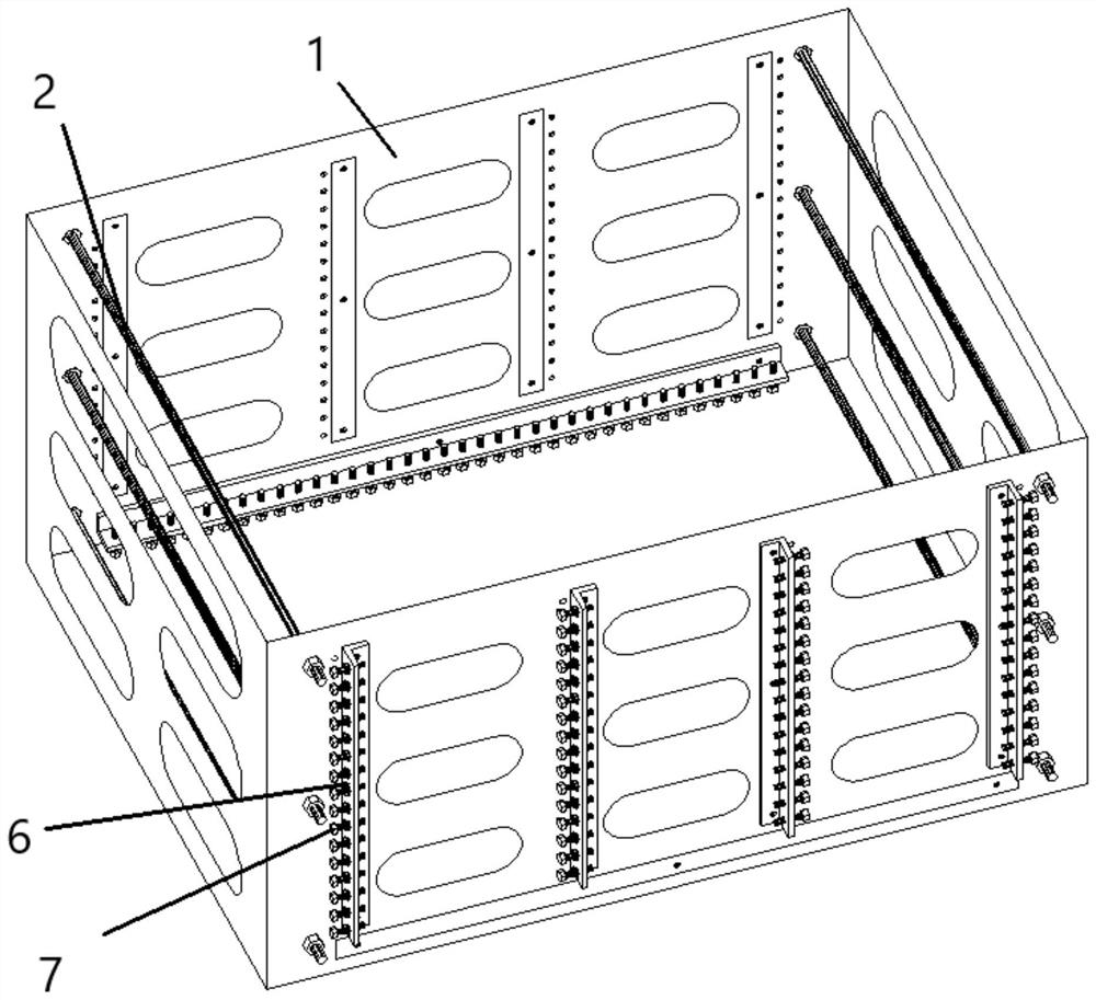
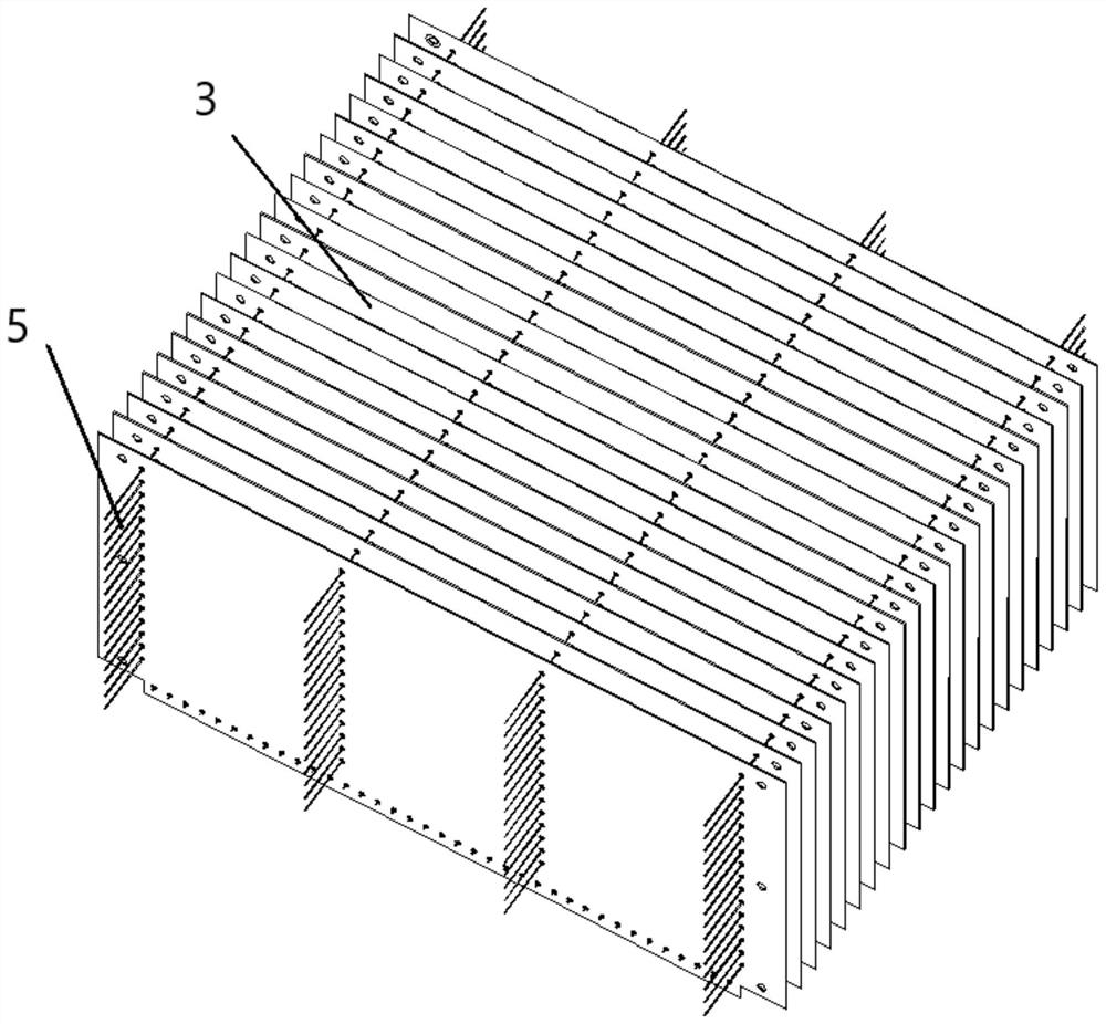
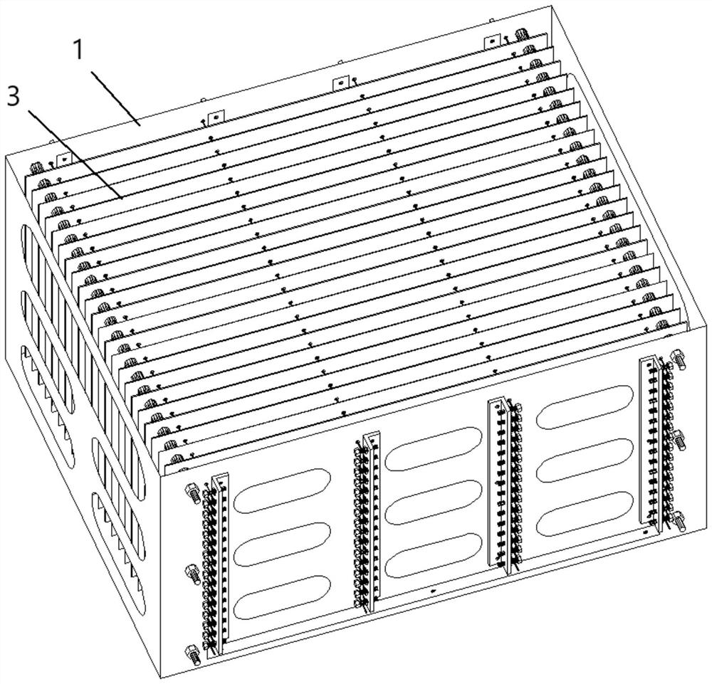
[0016] Such as Figures 1 to 3 as shown, figure 1 It is a structural schematic diagram of the outer frame body of a kind of UTG glass-ceramic plate tempered frame proposed by the present invention, figure 2 It is a structural schematic diagram of a ceramic partition of a UTG glass-ceramic plate tempered frame proposed by the present invention, image 3 It is a schematic diagram of the overall structure of a tempered frame of a UTG glass ceramic plate proposed by the present invention.

[0017] refer to Figures 1 to 3 , a kind of tempered frame of UTG glass-ceramic plate that the present invention proposes, comprises: outer frame body 1, a plurality of supporting rods 2, a plurality of ceramic separators 3;

[0018] A plurality of ceramic partitions 3 are arranged in the outer frame body 1 in parallel and at intervals in sequence, and a plurality of positioning holes respectively corresponding to the plurality of supporting links 2 are arranged on the ceramic partitions 3,...


PUM


Abstract

The invention discloses a UTG glass ceramic plate tempered frame which is characterized in that a plurality of ceramic partition plates are sequentially arranged in an outer frame body in parallel at intervals, a plurality of positioning holes corresponding to a plurality of supporting connecting rods are formed in the ceramic partition plates, the positioning holes in the ceramic partition plates correspond to one another, and isolation sleeves corresponding to the positioning holes are arranged between every two adjacent ceramic partition plates; and the supporting connecting rods sequentially penetrate through the positioning holes and the isolation sleeves correspondingly formed in the multiple ceramic partition plates, and the two ends of each supporting connecting rod are fixedly connected with the outer frame body. According to the UTG glass ceramic plate tempered frame with the optimized design, the glass is clamped in the outer frame body through the ceramic partition plates, so that poor effects caused by mutual contact are avoided, and due to the non-adhesion characteristic of the ceramic plates, the surface flatness of the UTG glass is effectively guaranteed, and the problems of surface pits and the like are solved.

Description

technical field [0001] The invention relates to the technical field of UTG glass tempering, in particular to an UTG glass ceramic plate tempering frame. Background technique [0002] As people become more and more dependent on mobile phones, the quality requirements for screen glass are getting higher and higher. 3D cover glass has replaced traditional soda-lime glass and has become a protective glass for mobile phones, tablets and other products. Among them, the tempered strength requirements for 3D cover glass have been increased. Therefore, in the production process of the industry, it is necessary to chemically strengthen part of the touch screen cover glass to increase its surface compressive stress, so as to improve its impact strength and bending strength. [0003] At present, during the operation process and subsequent cleaning process of the existing tempered frame, due to the thermal expansion of the glass sheet and the fixing rod under high temperature conditions...

Claims


Application Information

Patent Timeline
IPC IPC(8): C03C21/00
CPCC03C21/00
Inventor 吴建勇魏中凯
Owner 安徽金龙浩光电科技有限公司
Learn More