Filtering device with electrostatic spinning nanofiber cloth in bimodal distribution and mask
An electrospinning and nanofiber technology is applied in the field of filter devices and masks of electrospinning nanofiber cloth, which can solve the problems of inability to take into account the filtering effect and airflow resistance, and achieve the best barrier, smooth breathing, and improved bulkiness. , the effect of increasing the pore size
- Summary
- Abstract
- Description
- Claims
- Application Information
AI Technical Summary
Problems solved by technology
Method used
Image


Examples
Embodiment 1
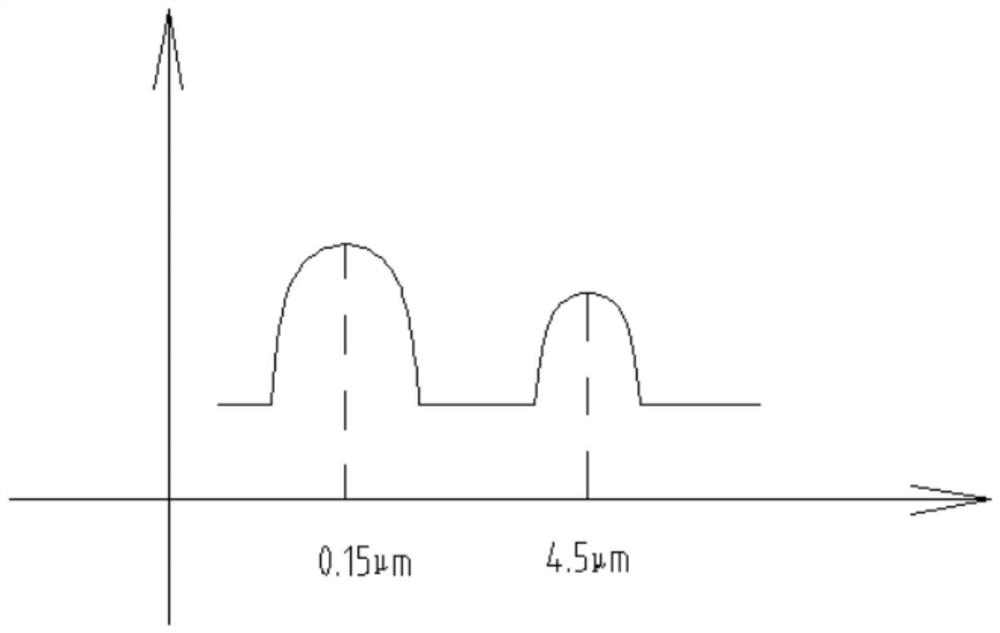
[0043] See attached Figure 1-5 , is a filter device 2 with bimodal distribution of electrospinning nanofiber cloth 22, including electrospinning nanofiber cloth 22 and melt blown non-woven fabric 21; described electrospinning nanofiber cloth 22 has the following characteristics: figure 1 The bimodal distribution.
[0044] Such as figure 2 Shown is a preferred embodiment, the melt-blown non-woven fabric 21 is disposed on one side of the electrospun nanofiber cloth 22 to support the electrospun nanofiber cloth 22 . When the melt-blown non-woven fabric 21 is one layer, the melt-blown non-woven fabric 21 and the electrospun nanofiber cloth 22 form a two-layer filter structure. A multilayer filter structure is formed with the electrospun nanofiber cloth 22 . In another embodiment, the meltblown nonwoven fabric 21 can also be disposed on both sides of the electrospun nanofiber fabric 22 at the same time.
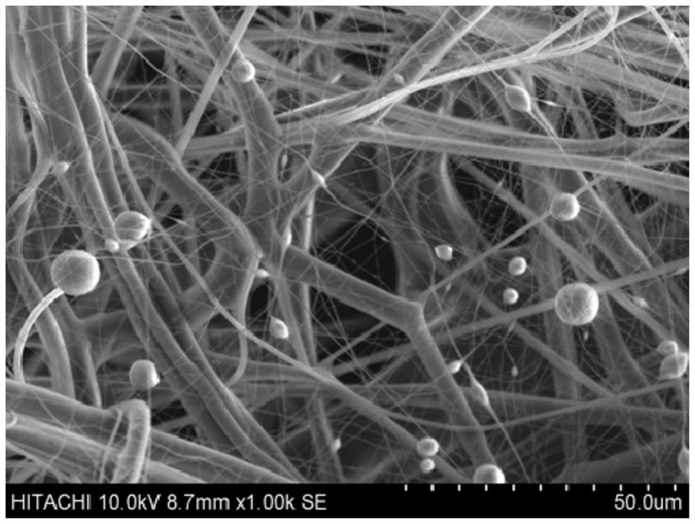
[0045] Such as image 3 As shown, the surface of the electrospun nanof...
Embodiment approach 1
[0049] The filter device 2 includes an electrospun nanofiber cloth 22 and a melt-blown non-woven fabric 21, and the diameter distribution of each fiber in the electrospun nanofiber cloth 22 has a statistically bimodal distribution form. The melt-blown non-woven fabric 21 is arranged on one side of the electrospun nanofiber cloth 22 to form a two-layer filter structure with the electrospun nanofiber cloth 22 . The bimodal distribution form includes: a first wave peak, the diameter range of the first wave peak is: 0.05-0.3 μm; a second wave peak, the diameter range of the second wave peak is: 3-6 μm. The peak value of the first peak is: 0.15 μm, and the peak value of the second peak is: 4.5 μm. The proportion of fibers whose diameter is within the range of the first peak is 80%, and the proportion of fibers whose diameter is within the range of the second peak is 20%. In the melt blown nonwoven fabric 21, the average diameter of each fiber was 7 micrometers.
comparative approach 1
[0051] Filtration device 2 comprises electrospinning nanofiber cloth 22 and melt-blown nonwoven fabric 21, and the diameter distribution of each fiber in electrospinning nanofiber cloth 22 is statistically randomly distributed, and each fiber in electrospinning nanofiber cloth 22 The diameter range is: 0.05 ~ 6μm. The melt-blown non-woven fabric 21 is arranged on one side of the electrospun nanofiber cloth 22 to form a two-layer filter structure with the electrospun nanofiber cloth 22. In the melt-blown non-woven fabric 21, the average diameter of each fiber is 7 μm.
PUM
| Property | Measurement | Unit |
|---|---|---|
| diameter | aaaaa | aaaaa |
| diameter | aaaaa | aaaaa |
| diameter | aaaaa | aaaaa |
Abstract
Description
Claims
Application Information
 - R&D
- Intellectual Property
- Life Sciences
- Materials
- Tech Scout
- Unparalleled Data Quality
- Higher Quality Content
- 60% Fewer Hallucinations
Browse by: Latest US Patents, China's latest patents, Technical Efficacy Thesaurus, Application Domain, Technology Topic, Popular Technical Reports.
© 2025 PatSnap. All rights reserved.Legal|Privacy policy|Modern Slavery Act Transparency Statement|Sitemap|About US| Contact US: help@patsnap.com