Blocking plate for hydrostatic test of steam turbine

A hydrostatic test and steam turbine technology, applied in the direction of applying stable tension/pressure to test the strength of materials, mechanical equipment, instruments, etc., can solve the problem that radial ribs cannot meet the bending resistance of blocking plates, and meet the bending resistance Effect

Active Publication Date: 2021-04-23
SHANDONG QILU ELECTRIC MOTOR MFG
View PDF6 Cites 0 Cited by
  • Summary
  • Abstract
  • Description
  • Claims
  • Application Information

AI Technical Summary

Problems solved by technology

[0004] In order to solve the problem that the radial ribs in the prior art cannot meet the bending resistance of the middle part of the blocking plate, the present invention provides a steam turbine hydraulic test blocking plate

Method used


Image

  • Blocking plate for hydrostatic test of steam turbine
  • Blocking plate for hydrostatic test of steam turbine
  • Blocking plate for hydrostatic test of steam turbine

Examples


Embodiment 1

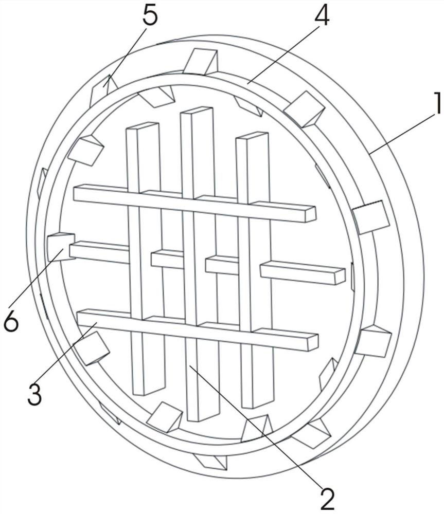
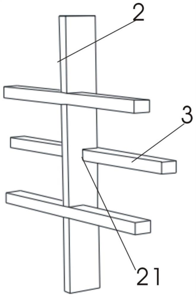
[0022] As shown in the drawings, a steam turbine hydrostatic test blocking plate includes a blocking plate body 1 and a rib set, the blocking plate body 1 is circular, and the rib set includes a first rib set and a second rib set The plate group, the first rib group and the second rib group are respectively composed of several single first rib ribs 2 and single second rib ribs 3 which are equal in number and spaced parallel to each other. They are arranged staggeredly in the middle of at least one side of the blocking plate body 1 , and the first rib rib 2 is provided with a notch 21 matching with the second rib rib 3 . The first rib group and the second rib group are interlaced in the middle of the blocking plate body 1, and at the same time, the connection strength between the first rib rib 2 and the second rib rib 3 is increased through the gap 21 to meet the requirements of the blocking plate. The bending resistance of the middle part in the hydrostatic test.

[0023] The...

Embodiment 2

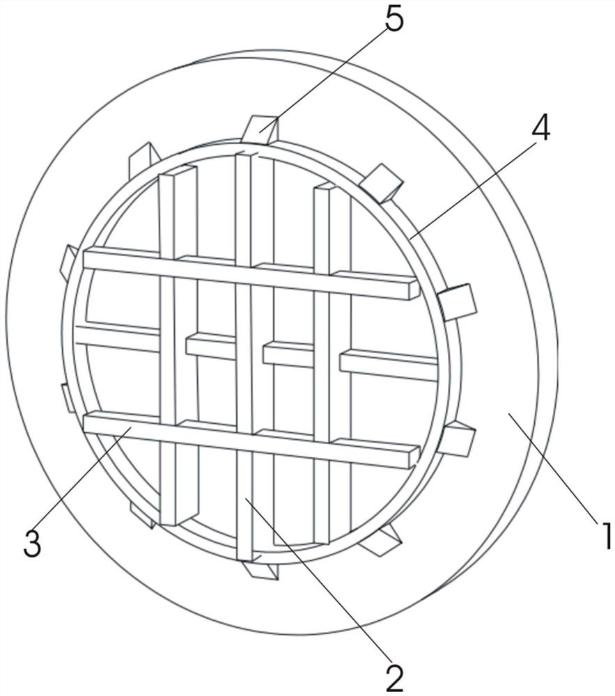
[0030] As shown in the figure, other things remain unchanged, the inner surface of the annular plate 4 is welded to the end of at least one first rib rib 2 and at least one second rib rib 3 . Further increase the structural strength of the annular plate 4 against the edge of the blocking plate body 1 .

[0031] A steam turbine hydrostatic test blocking plate according to the present invention is interlaced in the middle of the blocking plate body through the first rib group and the second rib group, and the ribs of the first rib and the second rib are added through the gap The connection strength of the ribs is to meet the bending resistance of the middle part of the blocking plate in the hydrostatic test.


PUM


Abstract

The invention discloses a blocking plate for a hydrostatic test of a steam turbine. The blocking plate comprises a blocking plate body and rib plate sets, wherein the blocking plate body is circular, and the rib plate sets comprise the first rib plate set and the second rib plate set; and the first rib plate set and the second rib plate set are respectively composed of a plurality of first rib plate ribs and second rib plate ribs, the first rib plate ribs and the second rib plate ribs are equal in number and parallel at intervals, the two rib plate sets are arranged in the middle of at least one side face of the blocking plate body in a staggered mode, and notches matched with the second rib plate ribs are formed in the first rib plate ribs. The first rib plate sets and the second rib plate sets are staggered in the middle of the blocking plate body, and meanwhile the connecting strength of the first rib plate ribs and the second rib plate ribs is improved through the notches, so that the anti-bending capacity of the middle of the blocking plate in the hydrostatic test is met.

Description

technical field [0001] The invention belongs to the technical field of hydraulic test blocking plates, in particular to a steam turbine hydraulic test blocking plate. Background technique [0002] The blocking plate in the prior art is cut into a circular shape from a steel plate, and the sealing groove is processed on the blocking plate body, which can be used for sealing the chamber during the hydrostatic test of the steam turbine. The ribs are cut into strips from steel plates, and multiple ribs are radially arranged on the blocking board body to enhance the bending resistance of the entire blocking board. A central block is provided at the center of the blocking plate body to connect the ribs together to prevent the weld seams from interfering with each other. [0003] The length of a single rib is smaller than the radius of the blocking plate, and the ribs arranged radially cannot effectively enhance the bending resistance of the middle of the blocking plate. When the ...

Claims


Application Information

Patent Timeline
Patent Type & Authority Applications(China)
IPC IPC(8): F16L55/115G01N3/02G01N3/12
CPCF16L55/115G01N3/02G01N3/12G01N2203/0003G01N2203/0019G01N2203/0048
Inventor 庄健龙国强吴玉昊崔萍刘小青
Owner SHANDONG QILU ELECTRIC MOTOR MFG
Why Eureka
Try Eureka