
Six-linkage polishing equipment and rear device and method thereof

A technology of six linkages and equipment, applied in the direction of grinding/polishing equipment, grinding drive device, grinding automatic control device, etc., can solve the problems of limited precision, limited processing, difficult polishing process, etc., and achieve high precision , low cost effect

Active Publication Date: 2021-04-23
枣庄北航机床创新研究院有限公司
View PDF5 Cites 3 Cited by
  • Summary
  • Abstract
  • Description
  • Claims
  • Application Information

AI Technical Summary

Problems solved by technology

Due to the poor rigidity and limited precision of the robot itself, it is difficult to polish the high-precision blades; the resolution of the abrasive belt grinder is limited due to the force control, and the replacement of the abrasive belt is inconvenient, so the rapid full-surface polishing of complex blades can be realized with high precision. Difficulty; superhard abrasive elastic polishing wheel polishing combined with multi-axis CNC machining machine tools can give full play to the advantages of high precision and high efficiency of CNC machine tools, and achieve high efficiency and high precision polishing of complex blades through fixed trajectory polishing routes. Because there are edge plates on the top and bottom of the blades and a damping table in the middle, it is difficult to avoid the interference between the tool holder and the workpiece with a five-axis machine tool, and the processing is limited.

Method used


Image

  • Six-linkage polishing equipment and rear device and method thereof
  • Six-linkage polishing equipment and rear device and method thereof
  • Six-linkage polishing equipment and rear device and method thereof

Examples


Embodiment Construction

[0064]Next, the technical solutions in the embodiments of the present invention will be apparent from the embodiment of the present invention, and it is clearly described, and it is understood that the described embodiments are merely embodiments of the present invention, not all of the embodiments. Based on the embodiments of the present invention, there are all other embodiments obtained without making creative labor without making creative labor premises.

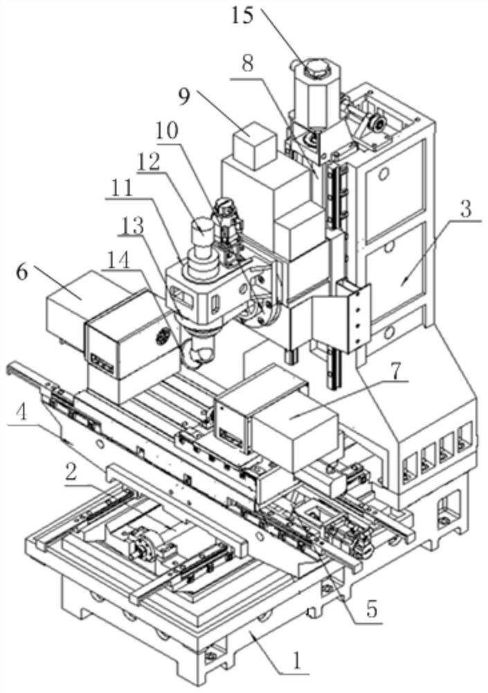
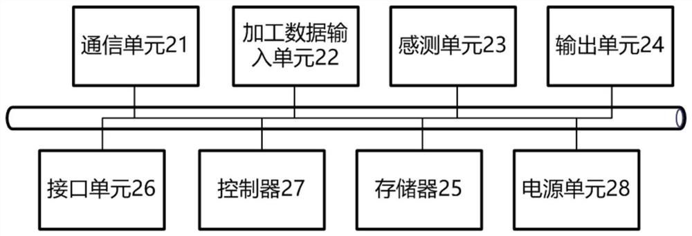
[0065]The present invention provides a six-link polishing apparatus and its post devices, such asfigure 1 withfigure 2 As shown, the base 1; the base 1 is mounted on the base 1, and the X-direction rail 2 is slidably connected to the slide rail 2; the longitudinal table 4 is provided with X-direction rail 2 The Y-to-rail 5 of the vertically disposed is fixed to one end of the slide rail 5, and the Y is slid to the slide rail 5 and there is a lateral table 7;

[0066]The fixed processing seat 6 is provided with a first clamping mecha...


PUM


Abstract

The invention provides six-linkage polishing equipment and a rear device and method thereof. The six-linkage polishing equipment comprises a base, wherein an X-direction sliding rail and a stand column are mounted on the base; a longitudinal worktable is connected to the X-direction sliding rail in a sliding manner; a Y-direction sliding rail perpendicular to the X-direction sliding rail is arranged on the longitudinal worktable; a transverse worktable is slidably connected to the Y-direction sliding rail; a Z-direction sliding rail is arranged on the stand column and arranged in the vertical direction; a vertical worktable is connected to the Z-direction sliding rail in a sliding manner; a turntable assembly is arranged on the vertical worktable; a wharf box is mounted on the turntable assembly; a main shaft penetrates through the wharf box; the lower end of the main shaft is arranged towards the transverse worktable; a cutter assembly is connected to the lower end of the main shaft; and the main shaft is connected with a main shaft rotation driving assembly. The degree of freedom of a traditional five-axis machine tool is expanded, the degree of freedom the same as that of a robot is achieved while the low cost and high precision of an original machine tool are kept, and the six-linkage polishing equipment can be completely qualified for full-profile high-precision automatic polishing of complex fan blades and the like.

Description

Technical field[0001]The present invention relates to the field of aircraft engine fan blades, and more particularly to a six-link polishing apparatus and a rear device and method thereof.Background technique[0002]Airplane engine fan blades include upper and lower edge plates, damping tables, transition fillets, intake edges, exhaust sides, etc., the surface is complicated, and there is still no artificial polishing method, but artificial polishing is high for workers' skills. Large labor intensity, polishing dust particles are particularly harmful to the human body, and the surface quality of the polished blade is relatively poor, consistent, low efficiency.[0003]In order to realize the full-profile automatic polishing of complex fan blades, the current automatic polishing method is polished by robot polishing, abrasive polishing polishing and super hard abrasive elastic polishing wheel polishing. The robot causing a poor stiffness, the accuracy is limited, and it is difficult to c...

Claims


Application Information

Patent Timeline
Patent Type & Authority Applications(China)
IPC IPC(8): B24B29/02B24B41/02B24B41/06B24B47/12B24B51/00B24B1/00
CPCB24B29/02B24B41/02B24B41/06B24B47/12B24B51/00B24B1/00
Inventor 崔传辉陈帅
Owner 枣庄北航机床创新研究院有限公司
Learn More