
Double-spindle drilling and tapping center

A dual-spindle and spindle technology, applied in the field of machine tools, can solve the problems of unfavorable space saving, high protection cost, and low rigidity

Pending Publication Date: 2021-04-23
GUANGZHOU CITY AGILE MFG
View PDF0 Cites 2 Cited by
  • Summary
  • Abstract
  • Description
  • Claims
  • Application Information

AI Technical Summary

Problems solved by technology

Moreover, because the drilling and tapping center requires high speed and the design of the moving parts is relatively small, the rigidity of the equipment is generally not high, and the existing drilling and tapping centers are not suitable for the processing of large parts and heavy cutting
In addition, the workbench of the existing drilling and tapping center moves back and forth, left and right, X-direction and Z-direction guide rails, screw rods, bearings, motors and other components are all in the processing area, equipment protection is relatively difficult, and there will be high protection costs and failures High efficiency, high maintenance costs and other shortcomings, and the existing drilling and tapping centers are single-spindle processing, when processing large parts, the processing efficiency is not high
[0004] In some multi-spindle drilling centers, the spindles are simply arranged side by side, and multiple processing spindles and tool magazines are installed side by side on the same machine base to achieve the purpose of processing multiple parts at the same time, but this type of machine tool In order to avoid mutual interference between the tool magazines, the distance between the spindles is often made very large, which is not conducive to saving space

Method used


Image

  • Double-spindle drilling and tapping center
  • Double-spindle drilling and tapping center
  • Double-spindle drilling and tapping center

Examples


Embodiment Construction

[0030] Embodiments of the present invention are described in detail below, and examples of the embodiments are shown in the drawings, wherein the same or similar reference numerals denote the same or similar elements or elements having the same or similar functions throughout. The embodiments described below by referring to the figures are exemplary only for explaining the present invention and should not be construed as limiting the present invention.

[0031] In the description of the present invention, it should be understood that the orientation descriptions, such as up, down, front, back, left, right, etc. indicated orientations or positional relationships are based on the orientations or positional relationships shown in the drawings, and are only In order to facilitate the description of the present invention and simplify the description, it does not indicate or imply that the device or element referred to must have a specific orientation, be constructed and operated in ...


PUM


Abstract

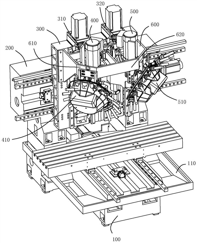
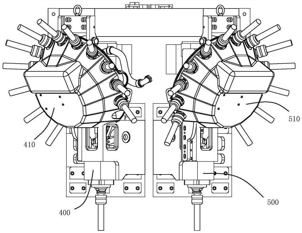
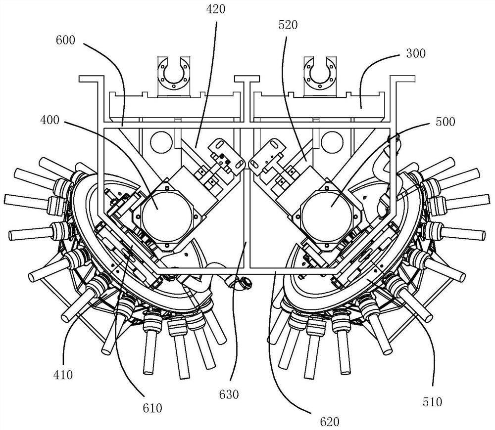
The invention discloses a double-spindle drilling and tapping center which comprises a machine tool body, a machine tool cross beam, a cross-shaped slipway, a first drilling and tapping spindle and a second drilling and tapping spindle, the first drilling and tapping spindle is driven by a first Z-direction lead screw assembly to move in the Z direction, a first tool magazine is arranged on the side surface of the first drilling and tapping spindle, the second drilling and tapping spindle is driven by a second Z-direction lead screw assembly to move in the Z direction, a second tool magazine is arranged on the side surface of the second drilling and tapping spindle, and the axis of the first tool magazine and the axis of the second tool magazine are separately arranged along two sides of the Y-axis. According to the double-spindle drilling and tapping center, the axes of the first tool magazine and the second tool magazine which are respectively matched with the first drilling and tapping spindle and the second drilling and tapping spindle are arranged separately on the machine tool body so that a maximum avoiding space is formed between the two tool magazines and between mounting structures of the two drilling and tapping spindles, when the double-spindle drilling and tapping center is used for machining two parts, interference between the two drilling and tapping spindles is avoided, the occupied space of the machine tool can be effectively saved, the machining efficiency of the machine tool is effectively improved, and the machine tool is applied to the technical field of machine tools.

Description

technical field [0001] The invention belongs to the technical field of machine tools, and more specifically relates to a double-spindle drilling and tapping center. Background technique [0002] The structure of the existing drilling and tapping centers is in the form of a C-type machine, that is, the workbench of the drilling and tapping center moves back and forth, left and right, and the spindle box moves up and down. The drilling and tapping centers of this structure need to obtain a higher fast moving speed. The size and quality of the workbench should not be too large. When the inertia of the equipment is large, the weight of the equipment base and the power of the driving motor need to be doubled due to the influence of the inertia when the equipment moves quickly, so the existing drilling and tapping center strokes are relatively small. [0003] Drilling and tapping centers with small strokes are basically used for the processing of small parts, such as the processi...

Claims


Application Information

Patent Timeline
Patent Type & Authority Applications(China)
IPC IPC(8): B23Q3/157B23Q1/01B23Q1/25
CPCB23Q3/157B23Q1/01B23Q1/25
Inventor 赵虎谢政平梁羡升王彦彪郭炜文
Owner GUANGZHOU CITY AGILE MFG
Learn More