Flexible machining clamp for automobile hub
A technology of flexible processing and automobile wheel hubs, which is applied in the direction of manufacturing tools, metal processing equipment, metal processing machinery parts, etc., can solve the problems that are still in its infancy, long adjustment time, reduced production efficiency, etc., and achieve small tolerance and material utilization The effect of high rate and improvement of processing efficiency
- Summary
- Abstract
- Description
- Claims
- Application Information
AI Technical Summary
Problems solved by technology
Method used
Image
Examples
Embodiment 1
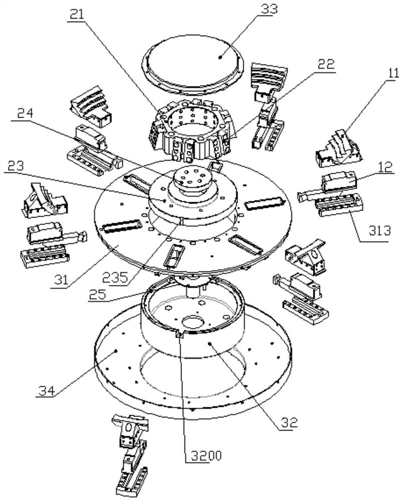
[0039] Such as Figure 1 to Figure 4 As shown, the automobile wheel hub flexible processing fixture of the present invention includes jaws 1, jaw driving base 2 and jaw disc 3, the middle part of jaw disc 3 is hollow, and jaw driving base 2 is installed on 6 hollow parts of jaw disc 3. parts. On the outer wall of the jaw driving seat 2 there are evenly distributed multiple sets of driving grooves 200 inclined along the axial direction of the jaw disc 3 for installing the jaws 1 . Multiple groups of jaws 1 are slidably connected to the jaw plate 3 along the radial direction of the jaw plate 3, each jaw 1 is provided with a sliding arm 12, the number of sliding arms 12 is the same as that of the driving groove 200, and each jaw 1 passes through The sliding arm 12 is slidably connected to a set of driving grooves 200, and each jaw 1 is provided with an arc-shaped jaw groove 100, which is an arc-shaped jaw groove distributed in a multi-step shape. Steps are used to match one siz...
Embodiment 2
[0043] The further optional design of this example is, as Figure 6 As shown, the inclination angle of the driving slot 200 is 11°-12° from bottom to top and inward; correspondingly, the sliding arm of each jaw also uses an inclined structure to fit and connect with the inclined surface of the driving slot 200 . The design of the inclination angle can realize the self-locking function of the clamp sliding arm 12 and the driving slot 200 when clamping. During the high-speed operation of the fixture, there will be no relative sliding between the two, which is stable and reliable.
Embodiment 3
[0045] The further optional design of this example is, as Figure 5 to Figure 8 , The jaw drive base 2 includes a drive slide 21 and a drive slide 22 . The tie rod assembly includes a guide disc 23 , a pressing plate 24 and a tie rod connecting seat 25 .
[0046] A guide structure is provided between the guide disc 23 and the base 32, the drive slide 21 and the guide disc 23 are fixedly connected by screws, the tie rod connection seat 25 passes through the guide disc 23 and is fixedly connected with the pressing plate 24, and the pressing plate 24 is set In the driving sliding seat 21 , the pressing plate 24 axially positions the tie rod connecting seat 25 on the guiding disc 23 . The guide disc 23 drives the jaw driving seat 2 to move directionally through the tie rod connecting seat 25 .
[0047] In the jaw driving seat 2, several installation grooves 211 are evenly distributed on the outer wall of the driving slider 21, and two driving sliders 22 are fixed in each install...
PUM
 Abstract
Description
Claims
Application Information
 - R&D
- Intellectual Property
- Life Sciences
- Materials
- Tech Scout
- Unparalleled Data Quality
- Higher Quality Content
- 60% Fewer Hallucinations
Browse by: Latest US Patents, China's latest patents, Technical Efficacy Thesaurus, Application Domain, Technology Topic, Popular Technical Reports.
© 2025 PatSnap. All rights reserved.Legal|Privacy policy|Modern Slavery Act Transparency Statement|Sitemap|About US| Contact US: help@patsnap.com


