Cylinder component hot-extrusion die and forming method

A hot extrusion die, hot extrusion technology, applied in the direction of metal extrusion die, metal extrusion, metal extrusion control equipment, etc., can solve problems such as difficulty in demoulding

Pending Publication Date: 2021-04-23
BEIJING HANGXING MACHINERY MFG CO LTD
View PDF7 Cites 0 Cited by
  • Summary
  • Abstract
  • Description
  • Claims
  • Application Information

AI Technical Summary

Problems solved by technology

[0004] In view of the above analysis, the embodiment of the present invention aims to provide a hot extrusion die and forming method for a cylindrical member to solve the difficulty in demoulding when extruding a deep cavity member with vertical and horizontal distribution of inner walls and high ribs in the prior art. question

Method used


Image

  • Cylinder component hot-extrusion die and forming method
  • Cylinder component hot-extrusion die and forming method
  • Cylinder component hot-extrusion die and forming method

Examples


Embodiment 1

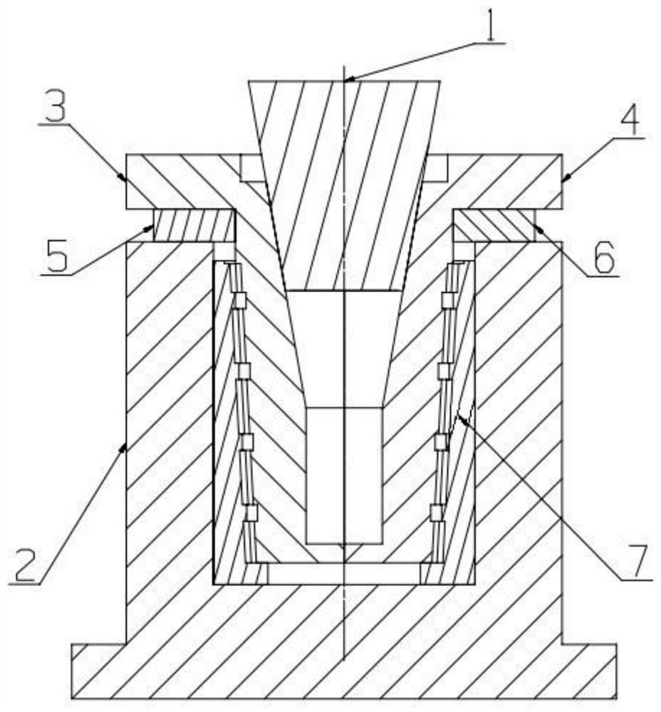
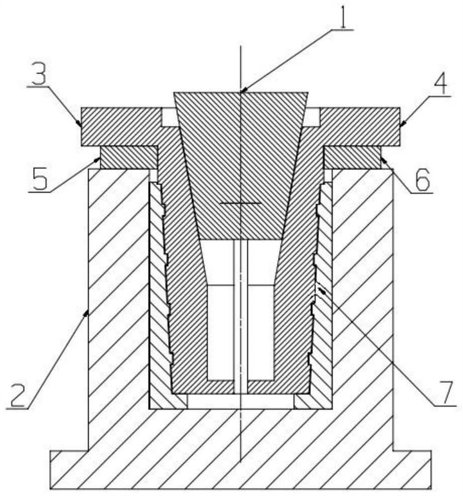
[0046] A specific embodiment of the present invention, combined with Figure 1-7 To illustrate, a hot extrusion die for a cylindrical member is disclosed, including: an upper die core 1 , a punch, a stop ring and a lower die 2 .

[0047] Furthermore, the outer surface of the upper mold core 1 is conical, the taper of the inclined surface is 1°-10°, and the height of the conical surface is 300mm-1000mm. The upper mold core 1 and the hydraulic cylinder equipped on the hydraulic press platform pass through the flange It is integrated with the bolt fastening, and the maximum movement stroke of the upper mold core 1 is 50mm-300mm.

[0048] Further, the punch includes a left punch 3 and a right punch 4, the left punch 3 and the right punch 4 are symmetrically arranged, installed on the upper mold platform of the hot extrusion equipment, the left punch 3 and the right punch 4 The surface of the inner cavity and the outer surface of the upper mold core 1 are in a wedge-shaped fit rel...

Embodiment 2

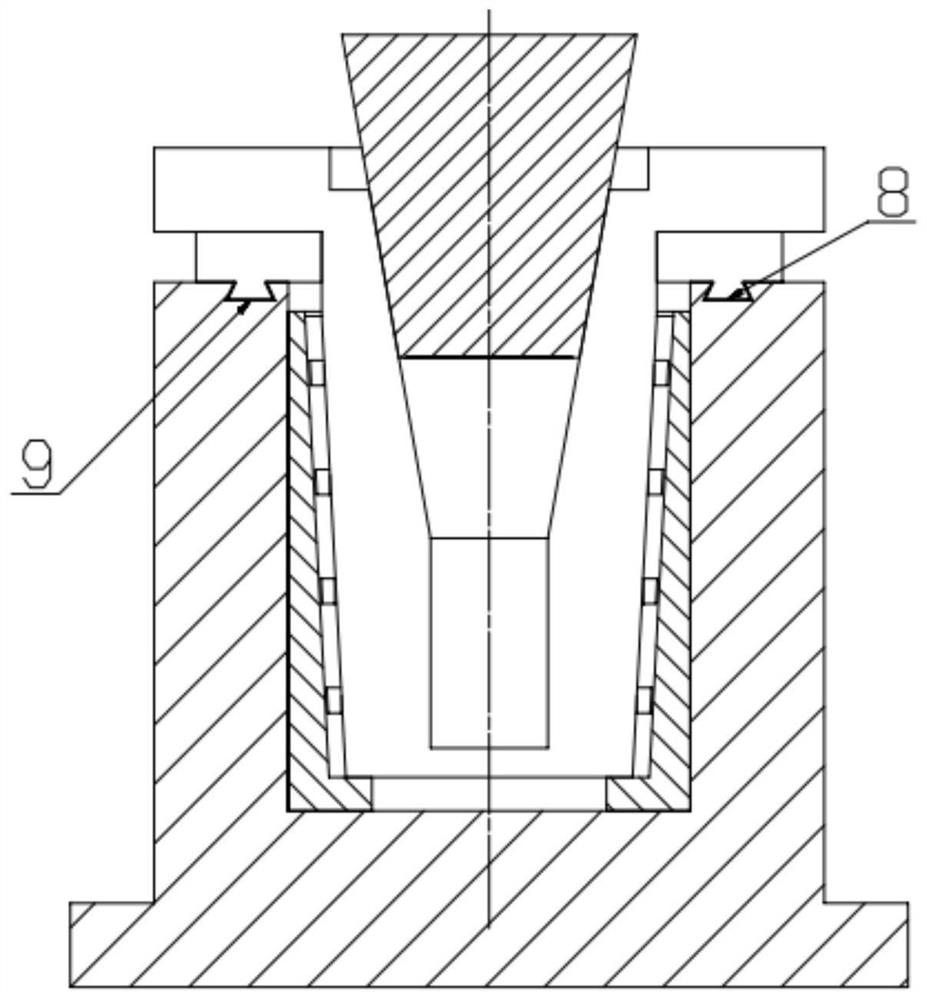
[0066] This embodiment provides a method for forming a hot extrusion die for a cylindrical member, mainly using the hot extrusion die for a cylindrical member provided in Example 1 to carry out composite hot extrusion forming on the extrusion blank of the cylindrical body, combined with the attached Figure 1-4 Instructions, including:

[0067] Step 1: Mold making. Manufacture and process hot extrusion dies based on the three-dimensional model of the cylindrical member that needs to be formed. The hot extrusion die includes: an upper die core 1, a punch, a limit ring, and a lower die 2, the punch includes a left punch 3 and a right punch 4, and the limit ring includes a left limit ring 5 symmetrically installed And right limit ring 6. The bottom end faces of the left limit ring 5 and the right limit ring 6 are provided with a slide rail 8 , and the upper end face of the lower mold 2 is provided with a slide groove 9 . According to the shape of the cylindrical member to be p...


PUM

PropertyMeasurementUnit
Taperaaaaaaaaaa
Heightaaaaaaaaaa
Draft angleaaaaaaaaaa

Abstract

The invention relates to a cylinder component hot-extrusion die and a forming method, and belongs to the technical field of hot extrusion dies. The problem of difficulty in demolding during hot extrusion forming of a deep-cavity barrel component with high ribs longitudinally and transversely distributed on the inner wall in the prior art is solved. The cylinder component hot-extrusion die comprises an upper die core, male dies, limiting rings and a lower die, the male dies comprise a left male die and a right male die, and are located on the two sides of the upper die core; the limiting rings comprise a left limiting ring and a right limiting ring, and are located on the outer side of the left male die and the outer side of the right male die separately; the male dies can be coupled with the inner surface of a cylinder component; the lower die can be coupled with the outer surface of the cylinder component; and a sliding groove is formed in the upper end face of the lower die. The problem difficulty in demolding during extrusion of the deep-cavity cylinder component with the high ribs longitudinally and transversely distributed on the inner wall in the prior art is solved.

Description

technical field [0001] The invention relates to the technical field of hot extrusion dies, in particular to a hot extrusion die for a cylinder member and a forming method. Background technique [0002] At present, products with overall modularization, complex appearance, and lightweight structure are more and more widely used in the aerospace field. For the deep-cavity inner-rib cylinder structure, hot extrusion technology is used for near-net shape manufacturing. Compared with the original traditional sheet welding, forging or casting + machining manufacturing technology, the fine structure dimensional accuracy and comprehensive mechanical properties are controlled. etc. have obvious advantages. Since the inner cavity of the deep cavity cylinder contains criss-cross vertical ribs, the draft angle between the local vertical ribs and the external curved surface is small after hot extrusion, and the size of the longitudinal ribs and transverse ribs is inconsistent, which make...

Claims


Application Information

Patent Timeline
IPC IPC(8): B21C23/02B21C25/02B21C29/00B21C31/00
CPCB21C23/02B21C25/02B21C29/00B21C31/00
Inventor 周小京李建伟王政杰郭晓琳王胜龙东栋
Owner BEIJING HANGXING MACHINERY MFG CO LTD
Why Eureka
Try Eureka