Rapid drying type printing equipment
A printing equipment and drying technology, which is applied in printing, printing machines, flatbed printing machines, etc., can solve the problems of not being able to dry quickly, manual adding of printing pigments, etc.
- Summary
- Abstract
- Description
- Claims
- Application Information
AI Technical Summary
Problems solved by technology
Method used
Image

Examples
Embodiment 1
[0065] A fast-drying type of printing equipment such as figure 1 As shown, it includes an underframe 1, an upper plate 2, a printing mechanism 3 and a drying mechanism 4, the underframe 1 is provided with an upper plate 2, the middle of the upper part of the underframe 1 and the middle of the bottom of the upper plate 2 are provided with a printing mechanism 3, and the upper plate 2. A drying mechanism 4 is provided on the left side of the top.
[0066] When printing workers want textile or paper strip printing materials to dry in a short period of time, they can use this quick-drying printing equipment. First, put the materials to be printed on the upper plate 2, and then start the printing mechanism 3. The printing mechanism 3 presses down to print the graphics and text on the textile or paper printing materials. When the printing mechanism 3 moves upward, people pull the printed part to the left, so that the printed matter is heated and dried by the drying mechanism 4. After...
Embodiment 2
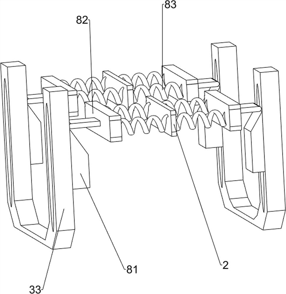
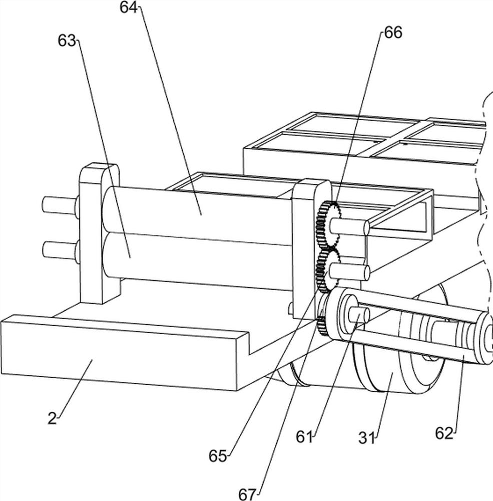
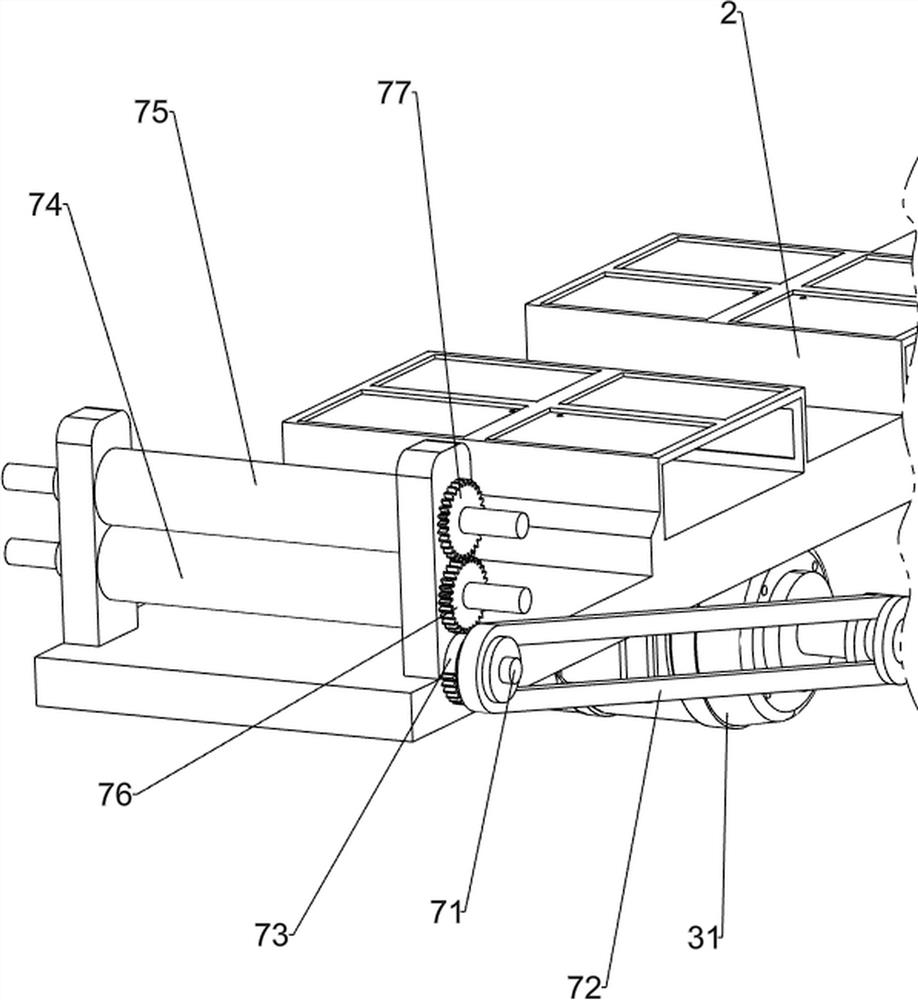
[0068] On the basis of Example 1, such as figure 2 and image 3 As shown, the printing mechanism 3 includes a motor 31, a cam 32, a connecting frame 33, a lower pressing plate 34 and a telescopic assembly 35, a motor 31 is installed in the middle of the bottom of the upper plate 2, and a cam 32 is arranged on the front and rear sides of the output shaft of the motor 31. Frame 1 upper middle sliding type is provided with connecting frame 33, and connecting frame 33 bottom front and rear sides all contact with the cam 32 of the same side, connecting frame 33 middle part left and right sides are all provided with lower pressure plate 34, connecting frame 33 middle part left and right sides Two telescopic assemblies 35 are connected between the bottom frame 1 and the top.
[0069] Start the motor 31, and the output shaft of the motor 31 rotates to drive the cam 32 to rotate. When the convex part of the cam 32 contacts the lower part of the connecting frame 33, the connecting fra...
Embodiment 3
[0073] On the basis of Example 2, such as Figure 4-8 Shown, also comprise discharging mechanism 5, upper plate 2 top right sides are provided with discharging mechanism 5, discharging mechanism 5 comprises shaped position frame 51, rotating round frame 52, putting material round rod 53, rotating shaft 54, Fixed frame 55 and latch 56, upper plate 2 top right front and back two parts are all provided with type position frame 51, the type position frame 51 top of front side is provided with rotating circular frame 52, rotating circular frame 52 and the type position frame of rear side 51 is connected with a round bar 53 for material placement in a rotating manner, and a rotating shaft 54 is provided on the left side of the upper part of the position frame 51 on the rear side, and a fixed frame 55 is provided on the rotating shaft 54. A latch 56 is provided.
[0074] People unplug the latch 56 upwards, and then turn the fixed frame 55 upwards, so that the textile or paper stri...
PUM
 Abstract
Description
Claims
Application Information
 - R&D
- Intellectual Property
- Life Sciences
- Materials
- Tech Scout
- Unparalleled Data Quality
- Higher Quality Content
- 60% Fewer Hallucinations
Browse by: Latest US Patents, China's latest patents, Technical Efficacy Thesaurus, Application Domain, Technology Topic, Popular Technical Reports.
© 2025 PatSnap. All rights reserved.Legal|Privacy policy|Modern Slavery Act Transparency Statement|Sitemap|About US| Contact US: help@patsnap.com