Oily sewage treatment method, oily sewage treatment system and construction method of oily sewage treatment system

A treatment method and technology of treatment system, which are applied in the field of oily sewage treatment method, treatment system and construction of treatment system, can solve problems such as oily sewage that has not been seen in chemical flooding, reduce viscosity and emulsified oil content, ensure standard treatment, raw materials A wide range of effects

Active Publication Date: 2021-04-16
大连知微生物科技有限公司
View PDF7 Cites 5 Cited by
  • Summary
  • Abstract
  • Description
  • Claims
  • Application Information

AI Technical Summary

Problems solved by technology

At present, it has been reported that the combined activated sludge anoxic and phosphorus-accumulating biofilm nitrification is used for phosphorus and nitrogen removal, but it has not been used for chemical flooding oily sewage treatment.

Method used


Image

  • Oily sewage treatment method, oily sewage treatment system and construction method of oily sewage treatment system
  • Oily sewage treatment method, oily sewage treatment system and construction method of oily sewage treatment system
  • Oily sewage treatment method, oily sewage treatment system and construction method of oily sewage treatment system

Examples


Embodiment 1

[0106] The construction method of the oily sewage treatment system of the present embodiment is as follows:

[0107] (1) Take 20L of activated sludge from a sewage treatment plant of a petrochemical company in Dalian, with a sedimentation ratio of 26%. The activated sludge is added to the biochemical tank, fed into the chemical flooding oily sewage, and pre-aerated for 12 days; it will account for 15% of the volume of the biochemical tank The supernatant was discharged, supplemented with chemical flooding oily sewage, and exposed for 48 hours. This process was repeated 8 times. The mass ratio of C, N, and P in the biochemical pool was kept at 100:5:0.8, and the water inflow rate was controlled at 2.5m 3 / h, continuous operation for 25 days to complete the acclimatization of activated sludge.

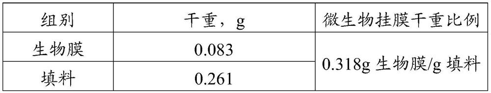
[0108] (2) The domesticated activated sludge is pumped into the upper water distributor and drenched, so that the activated sludge is repeatedly circulated in the simulated container of ...

Embodiment 2

[0114] The difference between the oily sewage treatment system of this embodiment and that of Embodiment 1 is that the inoculum ratio of Bacillus amyloliquefaciens and Bacillus Velesi is 10:1. After the oily sewage treatment system was stabilized, the total number of live bacteria of Bacillus amyloliquefaciens and Bacillus velesi on the biofilm was 1×10 11 piece / m 2 , the ratio of the number of live bacteria of Bacillus amyloliquefaciens and Bacillus Veles is 10:1.

Embodiment 3

[0116] The difference between the oily sewage treatment system of this embodiment and that of Embodiment 1 is that the ratio of the inoculum amounts of Bacillus amyloliquefaciens and Bacillus velesii is 0.5:1. After the oily sewage treatment system was stabilized, the total number of live bacteria of Bacillus amyloliquefaciens and Bacillus velesi on the biofilm was 1×10 12 piece / m 2 , the ratio of the number of live bacteria of Bacillus amyloliquefaciens and Bacillus Veles is 0.6:1.


PUM

PropertyMeasurementUnit
Removal rateaaaaaaaaaa
Oil removal rateaaaaaaaaaa

Abstract

The invention discloses an oily sewage treatment method which is characterized by comprising the following steps: treating oily sewage by using activated sludge; treating the treated oily sewage by using a biological membrane. The invention also discloses an oily sewage treatment system which is characterized by comprising a biochemical pool which is filled with activated sludge and is used for carrying out activated sludge treatment on oily sewage; a biological filter tank which contains a biological membrane and is used for carrying out biological membrane treatment on the oily sewage; a biochemical tank which is communicated with the biological filter tank. The invention also discloses a construction method of the oily sewage treatment system, which is characterized by comprising the following steps: domesticating activated sludge; preparation of biofilms. According to the treatment method, the yield of the sludge is greatly reduced while efficient and advanced treatment of the oily sewage is guaranteed, the water quality is stable, and the method belongs to a green and environment-friendly treatment method.

Description

technical field [0001] This application belongs to the technical field of environmental protection water treatment. In particular, it relates to a method for treating oily sewage, a treatment system and a construction method of the treatment system. Background technique [0002] In the field of oil and gas development, chemical flooding refers to the method of improving the recovery factor by adding polymers, surfactants and other agents to the injection fluid to change the properties of the displacement fluid and its mobility ratio with the reservoir fluid. . The wide application of chemical flooding tertiary oil recovery technology has led to the characteristics of complex composition, high viscosity and serious emulsification of oily sewage, which greatly increases the difficulty of treatment. At the same time, as the comprehensive water content of oilfields continues to increase in the middle and late stages of oil exploitation, the balance between the amount of produc...

Claims


Application Information

Patent Timeline
IPC IPC(8): C02F9/14
Inventor 赵静王静阿克巴尔·卡得拜孙秀鹏韩俊杰刘雨肖向晖
Owner 大连知微生物科技有限公司
Why Eureka
Try Eureka