Reinforced concrete waste treatment method
A technology for reinforced concrete and waste treatment, which is applied in the direction of grain processing, etc., can solve the problems of poor separation effect of reinforced concrete treatment, difficult separation, and mixed steel materials, so as to improve the treatment effect and operation efficiency, facilitate separation, and improve the treatment effect. Effect
- Summary
- Abstract
- Description
- Claims
- Application Information
AI Technical Summary
Problems solved by technology
Method used
Image
Examples
Embodiment 1
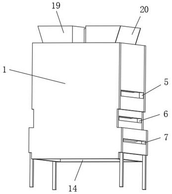
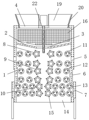
[0039] refer to Figure 1-5 , a reinforced concrete waste treatment method, comprising the following steps:
[0040] S1: The staff puts the reinforced concrete into the processing box 1 from the feeding mechanism manually or by using a feeding device;
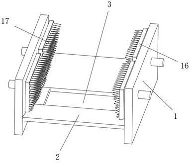
[0041] S2: The pre-crushing mechanism on the top of the processing box 1 pre-crushes the reinforced concrete waste fed in from the feeding mechanism, and the pre-crushed reinforced concrete falls from the slot 3 in the middle of the partition 2;
[0042] The top between the inner walls on both sides of the treatment box 1 is fixed with a partition 2, and the middle position of the partition 2 is provided with a through groove 3, and both sides of the outer wall of the top of the partition 2 are inclined downward toward the side close to the through groove;
[0043] S3: The waste material enters the crushing mechanism from the middle position, and the waste material enters the crushing cavity between the first crushing roller 8...
Embodiment 2
[0053] refer to Figure 1-8 , a reinforced concrete waste treatment method, during the operation of the pre-crushing mechanism and the crushing mechanism, the air flow mechanism in the treatment box 1 is used to accelerate the air flow in the treatment box 1;
[0054] The airflow mechanism is provided with a guide tube 22 that is rotatably connected to the middle position of the inner wall of the top of the treatment box 1. The top of the guide tube 22 is connected with a drive motor. The outer wall of the guide tube 22 is provided with a guide groove 23 of a spiral structure. The peripheral outer wall of the draft tube 22 is provided with a plurality of perforations 24, and the circumferential inner wall of the draft tube 22 is fixed with guide vanes 25 of a spiral structure. Rotate to cooperate with the guide groove 22 of the spiral structure on the outer wall to ventilate downward and bring part of the powder down to avoid dust at the feed inlet. Part of the powder enters t...
PUM
 Abstract
Description
Claims
Application Information
 - R&D
- Intellectual Property
- Life Sciences
- Materials
- Tech Scout
- Unparalleled Data Quality
- Higher Quality Content
- 60% Fewer Hallucinations
Browse by: Latest US Patents, China's latest patents, Technical Efficacy Thesaurus, Application Domain, Technology Topic, Popular Technical Reports.
© 2025 PatSnap. All rights reserved.Legal|Privacy policy|Modern Slavery Act Transparency Statement|Sitemap|About US| Contact US: help@patsnap.com


