
System and method for adjusting effective electromechanical coupling coefficient of ultrahigh-frequency bulk acoustic wave resonator

A bulk acoustic wave resonator, electromechanical coupling technology, applied in the direction of electrical components, impedance networks, etc., can solve the problems of large effective electromechanical coupling coefficient, excessive electromechanical coupling coefficient, large relative bandwidth of the filter, etc., to reduce the effective electromechanical coupling coefficient , weaken the effect of the piezoelectric effect

Pending Publication Date: 2021-04-13
武汉敏声新技术有限公司
View PDF0 Cites 0 Cited by
  • Summary
  • Abstract
  • Description
  • Claims
  • Application Information

AI Technical Summary

Problems solved by technology

The effective electromechanical coupling coefficient of UHF BAW resonators is very large, and the relative bandwidth of the filter built is also large, which makes it possible to use UHF and large bandwidth filters. However, due to the excessively large Electromechanical coupling coefficient, which makes it limited in the application of high-frequency narrow-band filters

Method used


Image

  • System and method for adjusting effective electromechanical coupling coefficient of ultrahigh-frequency bulk acoustic wave resonator
  • System and method for adjusting effective electromechanical coupling coefficient of ultrahigh-frequency bulk acoustic wave resonator
  • System and method for adjusting effective electromechanical coupling coefficient of ultrahigh-frequency bulk acoustic wave resonator

Examples


Embodiment Construction

[0021]The technical solutions in the embodiments of the present invention will be described below in conjunction with the embodiments of the present invention, and clearly, the described embodiments are merely embodiments of the invention, not all of the embodiments. Based on the embodiments in the present invention, all other embodiments obtained in the art without creative labor are not made in the premise of creative labor.

[0022]It should be noted that the features in the present invention in the present invention can be combined with each other in the case of an unable conflict.

[0023]The present invention will be further described below in connection with the specific embodiments, but is not limited as the present invention.

[0024]The method of adjusting the effective electromechanical coupling coefficient of the ultra-high frequency acoustic resonator is suitable for reducing the system of efficient electromechanical coupling coefficient of ultra high frequency acoustic resonato...


PUM


Abstract

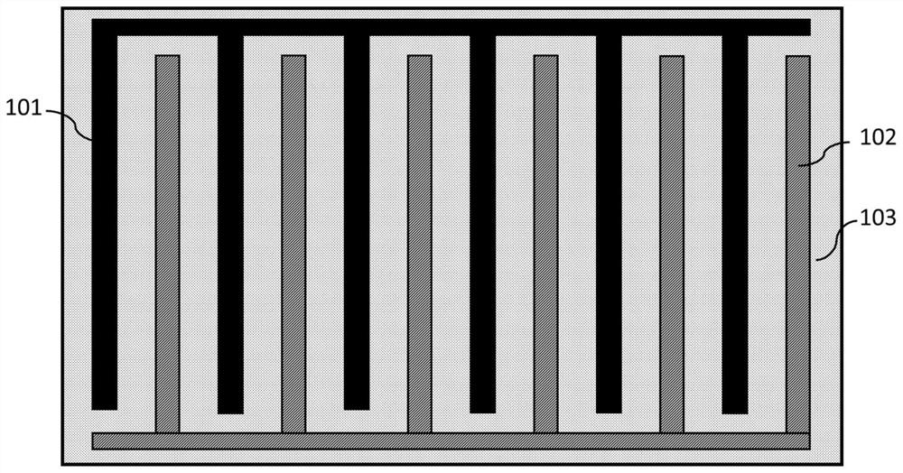
The invention relates to a technology for adjusting an effective electromechanical coupling coefficient of an ultrahigh-frequency bulk acoustic wave resonator, in particular to a system and a method for adjusting the effective electromechanical coupling coefficient of the ultrahigh-frequency bulk acoustic wave resonator. The system comprises a positive electrode, a negative electrode, a piezoelectric layer, a cavity and a substrate, the positive electrode and the negative electrode are sequentially and alternately arranged and are both arranged on the piezoelectric layer, and the piezoelectric layer is arranged on the substrate; at least one suspension electrode is arranged between the positive electrode and the negative electrode. Voltage with opposite polarities is added into the positive electrode and the negative electrode, a transverse electric field is excited between the positive electrode and the negative electrode, induced charges are generated on the surface of the suspension electrode under the action of the transverse electric field, a new electric field is formed between the suspension electrode and the positive electrode and the negative electrode, the intensity of an original transverse electric field is weakened, therefore the piezoelectric effect in the piezoelectric layer is reduced, and finally, the effective electromechanical coupling coefficient of the resonator is changed. The electromechanical coupling coefficient of the resonator can be adjusted by adjusting the thickness, width, number or material attribute of the suspension electrode, so that the resonator can be applied to a narrow-band filter.

Description

Technical field[0001]The present invention belongs to the ultra-high frequency acoustic resonator effective electromechanical coupling coefficient adjustment technology, and in particular, the system and method of adjusting the effective electromechanical coupling coefficient of ultra high frequency acoustic resonator.Background technique[0002]The rapid development of wireless and mobile communication systems, promoting rapid innovation of component performance and system integration technology. In order to achieve faster signal processing and reduce integrated complexity, miniaturization, and CMOS technology-compatible microelectromechanical system (MEMS) resonators have become a new generation of core devices, high-performance MEMS resonator technology as advanced wireless The basic components of the radio frequency front end of the communication system have a high demand.[0003]At present, the current RF filter is typically built by a sound surface wave resonator (SAW) and a film ...

Claims


Application Information

Patent Timeline
Patent Type & Authority Applications(China)
IPC IPC(8): H03H9/02H03H9/05H03H9/17
CPCH03H9/02H03H9/05H03H9/17
Inventor 孙成亮谢英王雅馨童欣谷曦宇龙开祥温志伟
Owner 武汉敏声新技术有限公司
Learn More