
Photo-thermal power station and wind power system considering carbon transaction, and low-carbon dispatching method and system

A technology of solar-thermal power station and wind power system, which is applied in the direction of power generation forecast in AC network, AC network circuit, load forecast in AC network, etc., and can solve problems affecting carbon emission, abandoned air volume and operation cost analysis, etc. , to achieve the effect of reducing carbon emissions

Pending Publication Date: 2021-04-13
NORTHEAST DIANLI UNIVERSITY +2
View PDF5 Cites 4 Cited by
  • Summary
  • Abstract
  • Description
  • Claims
  • Application Information

AI Technical Summary

Problems solved by technology

[0004] Existing studies have analyzed the role of low-carbon technologies such as photothermal and carbon trading mechanisms in curbing carbon emissions and promoting new energy consumption, which has certain theoretical and practical value, but there are still problems that can be further studied and discussed: 1) From the inside of the solar thermal power station, there is still insufficient analysis on how the joint operation of the electrothermal conversion link and the heat storage device affects the carbon emissions, the amount of abandoned air and the operating cost; The effect of the conversion link and the thermal power station sharing the rotating reserve of the thermal power unit to reduce carbon emissions and the impact on the overall cost of the system need further study; 3) There are few studies considering the combined operation of wind power, thermal power and solar thermal Low-carbon policies to further reduce the carbon emissions of the power system and improve the consumption level of wind power and solar heat

Method used


Image

  • Photo-thermal power station and wind power system considering carbon transaction, and low-carbon dispatching method and system
  • Photo-thermal power station and wind power system considering carbon transaction, and low-carbon dispatching method and system
  • Photo-thermal power station and wind power system considering carbon transaction, and low-carbon dispatching method and system

Examples


Embodiment 1

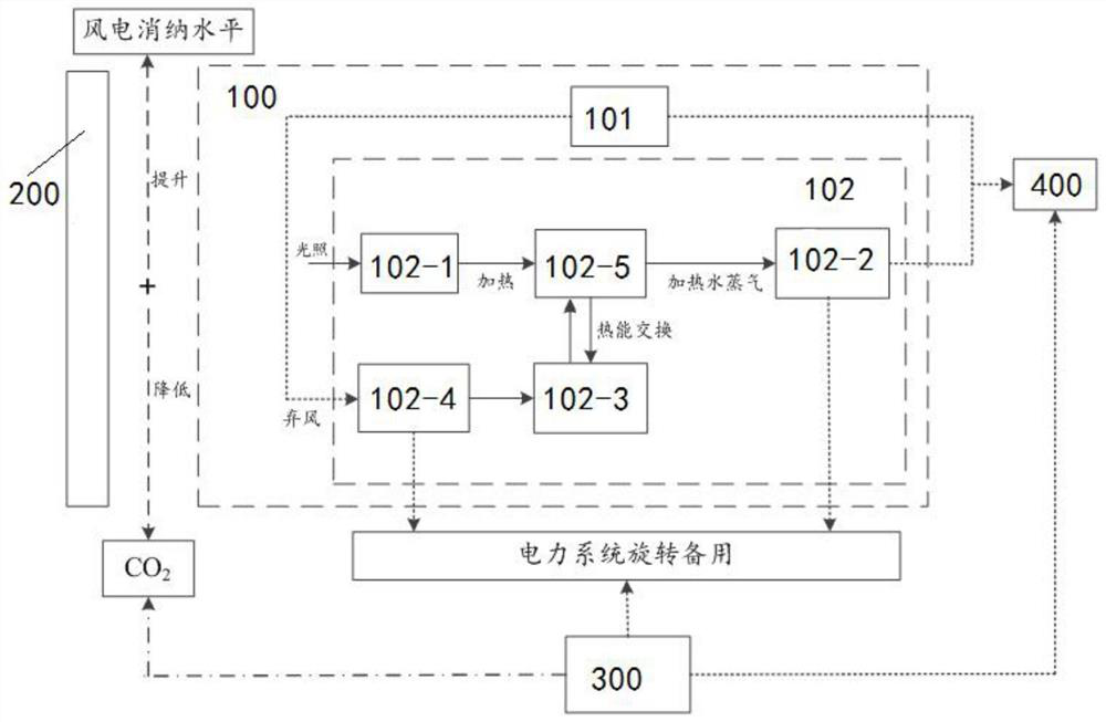
[0042]Such asfigure 1 As shown, the present embodiment proposes a photothermal power station and a wind power system 100 for carbon transactions, wherein the photothermatic power station and the wind power system 100 include wind farm 101 and photothermal power station 102, and the thermal power station 102 includes light field 102- 1, heat storage module 102-3, power conversion module 102-2, and electrical conversion module 102-4; light field 102-1 absorbing solar energy conversion to thermal energy, part of thermal energy through the thermal conductive die 102-5 by power conversion module 102-2 Converting into electrical energy supply grid 400, another portion of thermal energy is stored in the heat storage module 102-5; the wind farm 101 converts the abandoned wind power into heat through the electrothermal conversion module 102-4 and stored in the heat storage module 102 -3;

[0043]The photothermal power station 102, the electrothermal conversion module 102-4, and the thermofer se...

Embodiment 2

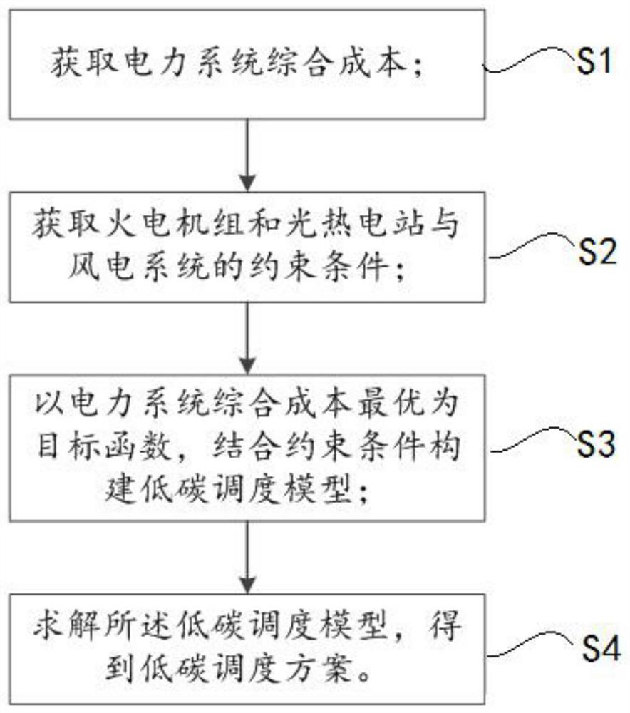
[0051]Such asimage 3 As shown, this embodiment provides a low-carbon scheduling method of a photothermal power station and a wind power system for carbon transactions, including:

[0052]Step S1: Get a comprehensive cost of the power system; the integrated cost of the power system includes carbon transaction costs, thermal power unit 300 operating cost, optical power plant operating cost, wind power operation cost, electric thermal conversion cost, and abandonment cost;

[0053]It can be further explained that (1) carbon transaction cost is:

[0054]

[0055]Where CpFor the carbon transaction cost; T number of time periods of the scheduling period; NGFor the number of fire motor groups 300; σ is the price of the right carbon discharge transaction;

[0056]DiI, t, h = ΔI, H PGi, T

[0057]Among them, δI, H The quota coefficient of the i-th thermoforming unit 300; DI, t, h PGi, T The carbon arrangement quota and output power of the i-th thermomechanical set 300 is respectively T-hours;

[0058]DiI, T = Δ...

Embodiment 3

[0160]Such asFigure 11 As shown, this embodiment provides a low-carbon scheduling system with a photothermal power plant and a wind power system 100, including carbon transactions, including:

[0161]The integrated cost of the power system is used to obtain comprehensive cost of power systems; the integrated cost of the power system includes carbon transaction costs, thermal power unit operating costs, operating costs of photothermal power station, cost of wind power operation, electricity conversion cost, and abandonment cost;

[0162]The power system constraint condition acquisition module M2 is used to obtain a constraint condition for the fire power unit 300 and the photothermal power station and the wind power system 100; the constraint conditions include power system power balance constraints, and the photothermal power station and the wind power system 100 operate constraint, power system rotation Constraints and trend constraints;

[0163]The low-carbon scheduling model build module ...


PUM


Abstract

The invention relates to a photo-thermal power station and wind power system considering carbon transaction, and a low-carbon economic dispatching method and system based on the system. Through the combined operation of wind power, thermal power and photo-thermal power, the photo-thermal power station shares the standby capacity borne by a thermal power unit, the carbon emission can be reduced, and the wind power consumption is promoted; the electricity-heat conversion link, the photo-thermal power station and the thermal power generating unit jointly provide spinning reserve for the system, the output of a traditional thermal power generating unit can be effectively reduced, then the carbon emission is reduced, the wind power consumption level is effectively improved, and meanwhile the economical efficiency of operation is guaranteed. In the low-carbon economic dispatching method and system, the optimal comprehensive cost of a power system is taken as an objective function, and a low-carbon dispatching model is constructed in combination with constraint conditions of all unit elements; and a low-carbon dispatching scheme is obtained based on the low-carbon dispatching model, so that low-carbon operation of the power system is facilitated.

Description

Technical field[0001]The present invention relates to the field of low-carbon scheduling techniques of power systems, and more particularly to a photothermal power station and a wind power system for carbon transactions, a low-carbon scheduling method and system of a light power plant and a wind power system based on a carbon transaction.Background technique[0002]In recent years, environmental pollution caused by carbon emissions has become increasingly serious, and low-carbon development has become a global consensus. In the face of severe ecological protection situations, my country has proposed a strategic goal of 2030 carbon emissions by 2030 to 60% to 65% in 2030.[0003]The implementation of low carbonization in power systems can be summarized as two aspects: technical aspects, such as new energy technology such as wind power and photothermal heat; in terms of policy, introduction of carbon transactions, improve market mechanisms. Coordination with two side coordination and can ...

Claims


Application Information

Patent Timeline
IPC IPC(8): H02J3/00H02J3/46H02J3/28G06Q10/06G06Q50/06
CPCH02J3/0075H02J3/008H02J3/466H02J3/28H02J3/003H02J3/004G06Q10/06312G06Q10/06315G06Q50/06H02J2203/20H02J2203/10H02J2300/22H02J2300/28H02J2300/40Y02E10/76Y02E70/30
Inventor 崔杨邓贵波唐耀华仲悟之宋丹赵钰婷郝涛
Owner NORTHEAST DIANLI UNIVERSITY
Learn More