
Tooling clamp for gear grinding of gear with shaft and alignment method

A technology for tooling fixtures and gears, which is applied in gear tooth manufacturing devices, belts/chains/gears, manufacturing tools, etc. It can solve problems such as high coaxiality requirements, pressure relief, workpiece dumping, etc., and achieve the effect of concentricity

Active Publication Date: 2021-04-13
袁海滨
View PDF16 Cites 0 Cited by
  • Summary
  • Abstract
  • Description
  • Claims
  • Application Information

AI Technical Summary

Problems solved by technology

[0004] Most of the current methods of gear grinding for a gear with a shaft are: use the concentric upper and lower jacks of the machine tool to tighten the gear shaft, and set a pressure plate or other fixing mechanism on the lower part of the gear shaft to fix it with the workbench, so as to Guarantee its stability in the process of being processed; however, this clamping method has higher requirements on the pressure and coaxiality of the upper hydraulic thimble of the machine tool. With the increase of the use time of the machine tool, the hydraulic system is aging and prone to pressure relief. At this time, the coaxiality of the machined shaft gear will not be guaranteed. If the gear setting is high and the overall center of gravity is too high, the workpiece will be dumped during the rotation of the worktable, thereby smashing the machine tool. Its safety is worthwhile. Discussion; moreover, when the upper and lower tapered thimbles are used to cooperate with the center hole of the gear shaft, the machining accuracy of the tapered center hole is also very high. If there is a machining deviation, it will cause the gear to be processed It is always in a deviated state; and due to the long-term friction between the thimble and the center hole, the thimble will be worn. In the case of wear, even if the taper of the center hole is consistent with the original design of the thimble, and the coaxiality with the gear is within the specified range, The overall deviation of the gear will also occur; in the machining workshop, there are many iron slags, which often fall into the center hole of the gear shaft. When clamping with a thimble, the top deviation will occur due to the existence of iron slag , in this state, alignment will shift the entire gear shaft
Therefore, there are many disadvantages in this clamping method, which needs to be further improved.

Method used


Image

  • Tooling clamp for gear grinding of gear with shaft and alignment method
  • Tooling clamp for gear grinding of gear with shaft and alignment method
  • Tooling clamp for gear grinding of gear with shaft and alignment method

Examples


Embodiment Construction

[0050] In order to more clearly understand the above objects, features and advantages of the present invention, the present invention will be described in detail below in conjunction with the accompanying drawings and specific embodiments. It should be noted that, in the case of no conflict, the embodiments of the present application and the features in the embodiments can be combined with each other.

[0051] In the description of the present invention, it should be noted that the terms "center", "upper", "lower", "left", "right", "vertical", "horizontal", "inner", "outer" etc. The indicated orientation or positional relationship is based on the orientation or positional relationship shown in the drawings, or the orientation or positional relationship that is usually placed when the product of the invention is used, and is only for the convenience of describing the present invention and simplifying the description, rather than indicating or implying References to devices or e...


PUM


Abstract

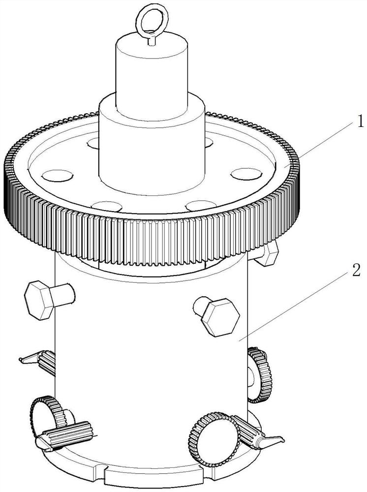
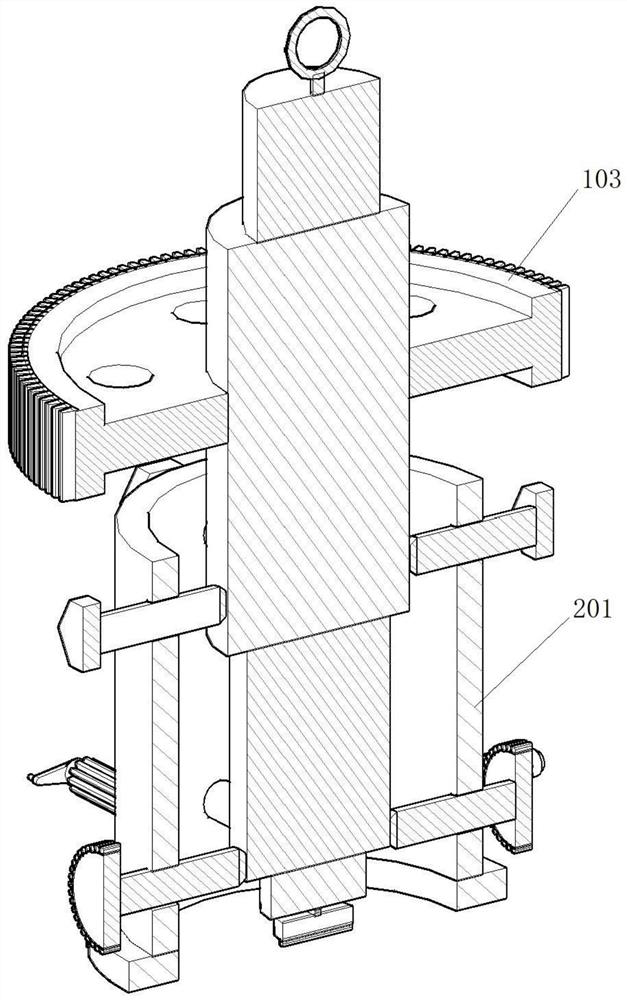
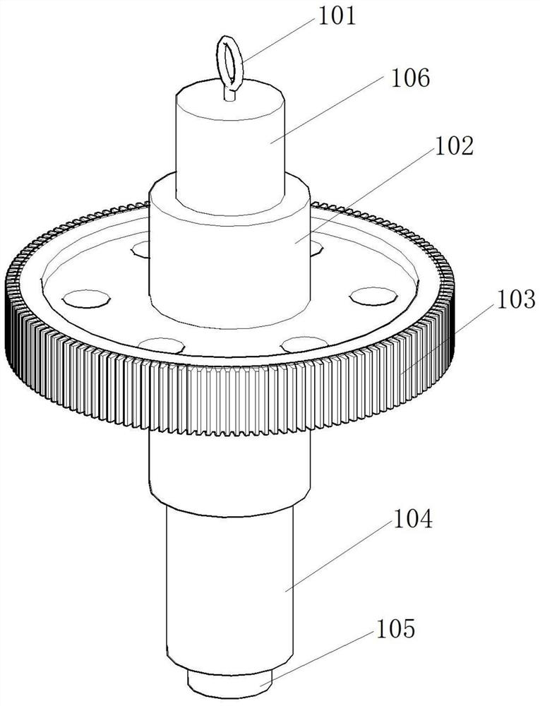
The invention provides a frock clamp for gear grinding of a gear with a shaft and an alignment method, the frock clamp comprises a clamping tank body and at least three adjustable fastening mechanisms, the adjustable fastening mechanisms are uniformly distributed at the upper part and the lower part of the clamping tank body, and used for adjusting the coaxiality of a gear shaft and a workbench; each adjustable fastening mechanism comprises an adjustable fastening piece and a fine adjustment mechanism; the adjustable fastening piece is arranged on the upper portion and used for adjusting the overall position of the gear shaft; and the fine adjustment mechanism is arranged on the lower portion and used for conducting coaxiality fine adjustment on the upper end of the gear shaft. The technical problems of low clamping safety, unstable clamping and the like caused by a traditional ejector pin type gear grinding clamping mode are effectively solved.

Description

technical field [0001] The invention belongs to the technical field of gear grinding fixtures, and in particular relates to a tooling fixture for gear grinding with a shaft and an alignment method. Background technique [0002] The gear grinding process is the last process in the gear forming process, that is, the finishing process. The specific concept is: the process of grinding the gear teeth with a gear grinding machine is called gear grinding. Grinding processing is divided into: internal tooth grinding and external tooth grinding of cylindrical gear straight teeth; internal tooth grinding and external tooth grinding of cylindrical gear helical gears, and grinding of conical bevel gears. Gear grinding machine is a metal cutting machine tool for gear finishing. Use the grinding wheel as a tool to grind (form grinding) the tooth surface of the gear that has been hobbed or shaped to improve the precision and surface finish of the gear. It is suitable for finishing steel...

Claims


Application Information

Patent Timeline
Patent Type & Authority Applications(China)
IPC IPC(8): B23F23/06B23F23/00
CPCB23F23/06B23F23/00
Inventor 袁海滨
Owner 袁海滨
Learn More