Axial loading device and bearing test bench
An axial loading and axial technology, which is applied in mechanical bearing testing and other directions, can solve problems such as inability to simulate bearings and affect the accuracy of test results, and achieve the effect of ensuring accuracy
- Summary
- Abstract
- Description
- Claims
- Application Information
AI Technical Summary
Problems solved by technology
Method used
Image
Examples
Embodiment 1
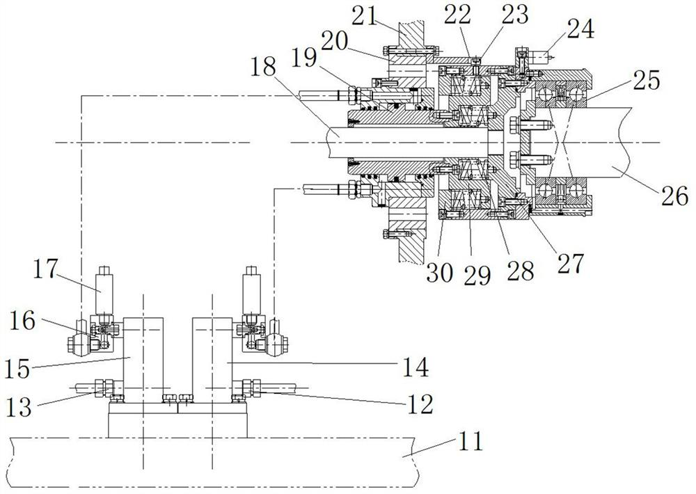
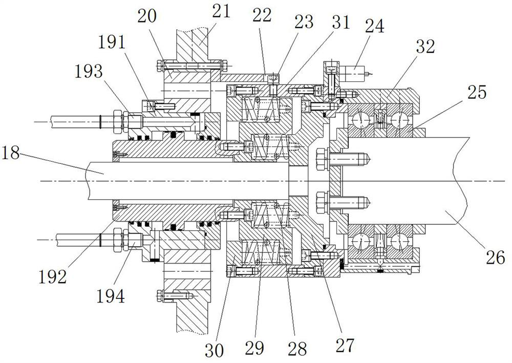
[0058] Such as figure 1 and figure 2 As shown, the bearing test bench includes a frame body 21, a main shaft support is arranged inside the frame body 21, a main shaft 26 is arranged on the main shaft support, and the axial direction of the main shaft 26 is the front and rear direction, and the rear end of the main shaft 26 is provided with an axial loading device and vibration device, the front end of the main shaft 26 is provided with a main shaft driving device, and the main shaft driving device is used to drive the main shaft 26 to rotate.
[0059] In this embodiment, the rear end of the main shaft 26 is provided with a bearing 25 to be tested, the inner ring of the bearing 25 to be tested is fixed on the main shaft 26, and its outer ring is fixed on the holder 32; The outer ring of the bearing 25 applies an axial loading force, and the vibration device is used to provide vibration to the bearing 25 to be tested. Wherein, a vibration sensor 24 is fixed on the fixing sea...
Embodiment 2
[0074] The difference between this embodiment and Embodiment 1 is that in Embodiment 1, the driving cylinder is an annular loading cylinder 19, and the annular loading cylinder 19 includes a plunger 192, the front end of the plunger 192 is fixedly connected with the loading plate 29, and the plunger 192 has a hollow cavity body, the loading rod 18 passes through the hollow cavity and is connected to the front end cover 27 in transmission. In this embodiment, based on the transmission connection between the loading rod and the front end cover, the driving cylinder is a common oil cylinder. There are at least two common oil cylinders arranged at intervals along the circumference of the loading rod. The driving end of the common oil cylinder is in transmission connection with the loading plate.
Embodiment 3
[0076] The difference between this embodiment and Embodiment 1 is that in Embodiment 1, the loading end cover includes a front end cover 27 and a rear end cover 30, the annular loading oil cylinder 19 includes a plunger 192, and the front end of the plunger 192 is fixedly connected with the loading plate 29, and the loading A compression spring is provided between the plate 29 and the corresponding end cap to realize the transmission. In this embodiment, the front end of the plunger is not provided with a loading plate, but is directly fixedly connected with the front cover to realize transmission. In other embodiments, no rear cover may be provided.
PUM
 Abstract
Description
Claims
Application Information
 - R&D Engineer
- R&D Manager
- IP Professional
- Industry Leading Data Capabilities
- Powerful AI technology
- Patent DNA Extraction
Browse by: Latest US Patents, China's latest patents, Technical Efficacy Thesaurus, Application Domain, Technology Topic, Popular Technical Reports.
© 2024 PatSnap. All rights reserved.Legal|Privacy policy|Modern Slavery Act Transparency Statement|Sitemap|About US| Contact US: help@patsnap.com


