
Sound-blocking sheet member, sound-blocking structure using same, and method for manufacturing sound-blocking sheet member

A manufacturing method, technology of sheet parts, applied in the field of soundproof sheet parts

Pending Publication Date: 2021-04-09
MITSUBISHI CHEM CORP
View PDF4 Cites 2 Cited by
  • Summary
  • Abstract
  • Description
  • Claims
  • Application Information

AI Technical Summary

Problems solved by technology

However, in the method of increasing the mass of vibration-proof and sound-insulating materials, the amount of noise reduction is limited by the mass constraints of buildings, vehicles, etc.

Method used


Image

  • Sound-blocking sheet member, sound-blocking structure using same, and method for manufacturing sound-blocking sheet member
  • Sound-blocking sheet member, sound-blocking structure using same, and method for manufacturing sound-blocking sheet member
  • Sound-blocking sheet member, sound-blocking structure using same, and method for manufacturing sound-blocking sheet member

Examples


no. 1 approach

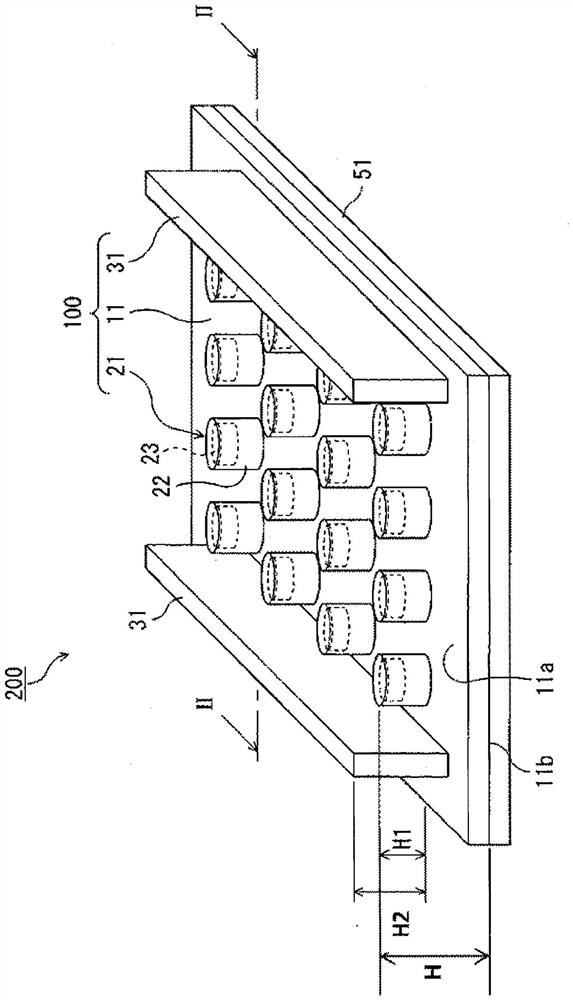
[0169] figure 1 and image 3 It is a schematic perspective view which shows the sound insulation sheet member 100 and the sound insulation structure 200 of this embodiment, and its II-II arrow cross-sectional view. The soundproof sheet member 100 includes: a sheet 11 having rubber elasticity; a plurality of resonance portions 21 provided on the sheet surface 11a of the sheet 11 so as to be in contact with the sheet surface 11a; At least one rib-shaped protrusion 31 on 11a. The sound-insulating sheet member 100 is supported by the support body 51 provided on the sheet surface 11 b side of the sheet 11 , thereby constituting the sound-insulating structure 200 .

[0170]In the sound-insulating sheet member 100 and the sound-insulating structure 200 , for example, when a sound wave is injected from a noise source on the side of the supporting body 51 , resonance of the sheet 11 and / or the resonance portion 21 occurs. At this time, there may be a frequency region in which the di...

no. 2 approach

[0259] Figure 8 It is a schematic perspective view which shows the sound insulation sheet member 101 and the sound insulation structure 201 of this embodiment, and its arrow cross-sectional view. In this embodiment, the sound-insulating sheet member 100 and the sound-insulating structure of the above-mentioned first embodiment are different except that the number of resonance parts, the shape of the base part and the weight part, and the shape and number of the rib-shaped protrusions are different. Body 200 has the same structure, so repeated descriptions are omitted here.

[0260] The resonator 21 of the present embodiment is constituted by a composite structure including a base 24 and a weight 25 supported by the base 24 and having a mass greater than that of the base 24 . In the present embodiment, a plurality of bases 24 having a substantially cylindrical outer shape are also provided on the sheet surface 11 a of the sheet 11 so as to be in contact with the sheet surface...

Embodiment 1

[0323] Example 1 is to include Figure 10A A single unit including the sound insulation sheet parts shown. Table 1 shows the dimensions, materials, and physical properties of the components of the unit cells. The acoustic band gap in the unit monomer is calculated based on the above calculation method.

[0324] As a result of calculation, in Example 1, the acoustic bandgap was 3461-4551 Hz and the normalized acoustic bandgap width was 0.27, and it was confirmed that there is a sufficient sound-insulating bandwidth.


PUM

PropertyMeasurementUnit
heightaaaaaaaaaa
heightaaaaaaaaaa
thicknessaaaaaaaaaa

Abstract

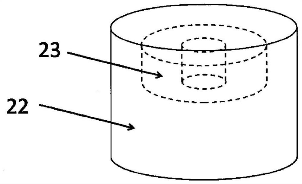
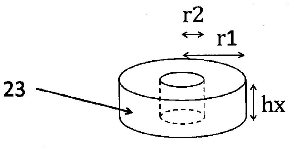
The objective of the present invention is to provide a sound-blocking sheet member that has high sound-blocking performance exceeding the law of mass while being relatively lightweight, and has excellent manufacturability and durability. The sheet member has at least a sheet and a plurality of resonant parts. The resonant parts are provided in contact with a sheet surface of the sheet, and the resonant parts are provided with a weight section and a base section. The weight section is supported by the base section and has greater mass than the base section, and the weight section has a through portion. The base section makes contact with the surface of the weight section which is on the tip-end side of the resonant part, and covers the weight section.

Description

technical field [0001] The present invention relates to a sound insulating sheet member, a sound insulating structure using the sound insulating sheet member, and a method for manufacturing the sound insulating sheet member. [0002] This application claims priority based on Japanese Patent Application No. 2018-166867 filed on September 6, 2018 and Japanese Patent Application No. 2019-148471 filed on August 13, 2019, and the contents thereof are cited here. Background technique [0003] In complex housing, office buildings, hotels and other buildings, it is required to block outdoor noise from automobiles, railways, airplanes, ships, etc., equipment noise generated inside the building, and human voices to meet the quietness of the room. In addition, in vehicles such as automobiles, railways, airplanes, and ships, it is necessary to reduce indoor noise in order to block wind noise and engine sound and provide occupants with a quiet and comfortable space. Therefore, research ...

Claims


Application Information

Patent Timeline
Patent Type & Authority Applications(China)
IPC IPC(8): G10K11/16B32B3/24B32B25/04E04B1/82G10K11/162G10K11/172
CPCE04B1/82G10K11/162G10K11/172B29C39/10B29K2995/0002B29K2021/00B32B23/046B32B27/308B32B25/20B32B25/04B32B2250/02B32B15/095B32B2307/54B32B27/18B32B27/34B32B25/08B32B2419/00B32B2307/732B32B2307/51B32B2274/00B32B2605/08B32B15/06B32B27/302B32B25/16B32B23/08B32B15/088B32B2605/18B32B15/082B32B27/32B32B27/38B32B27/281B32B2307/102B32B2270/00B32B15/18B32B2605/12B32B25/14B32B27/22B32B27/40B32B23/20B32B27/06B32B27/36B32B15/20B32B3/30B32B27/283B32B25/12B32B15/09B32B15/085B32B27/304B32B27/08B32B2250/24B32B27/20B32B17/06B29L2031/30B32B3/266B32B2605/00B60R13/0815E04B1/8409
Inventor 杉浦克彦古贺尚悟内田直幸井上一真加藤幸男上原幸治三浦仁
Owner MITSUBISHI CHEM CORP
Learn More