
Resistor-capacitor RC oscillator

A resistor-capacitor and oscillator technology, applied in the field of resistor-capacitor RC oscillators, can solve problems such as poor clock frequency stability

Active Publication Date: 2021-04-09
HYGON INFORMATION TECH CO LTD
View PDF10 Cites 1 Cited by
  • Summary
  • Abstract
  • Description
  • Claims
  • Application Information

AI Technical Summary

Problems solved by technology

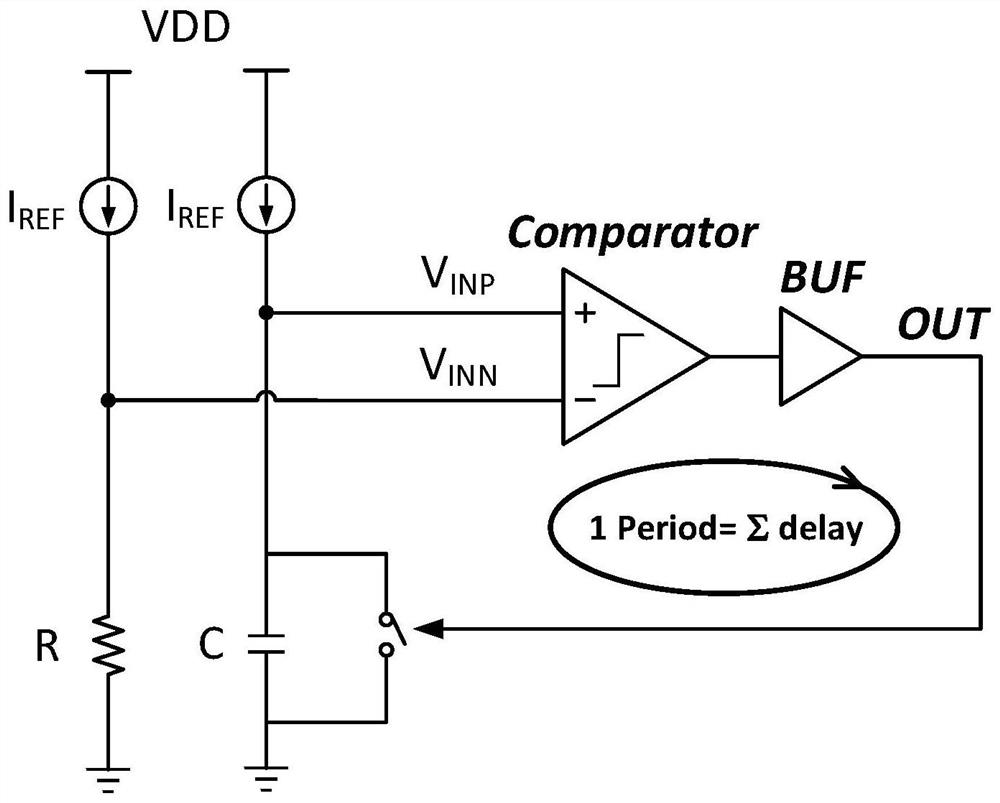
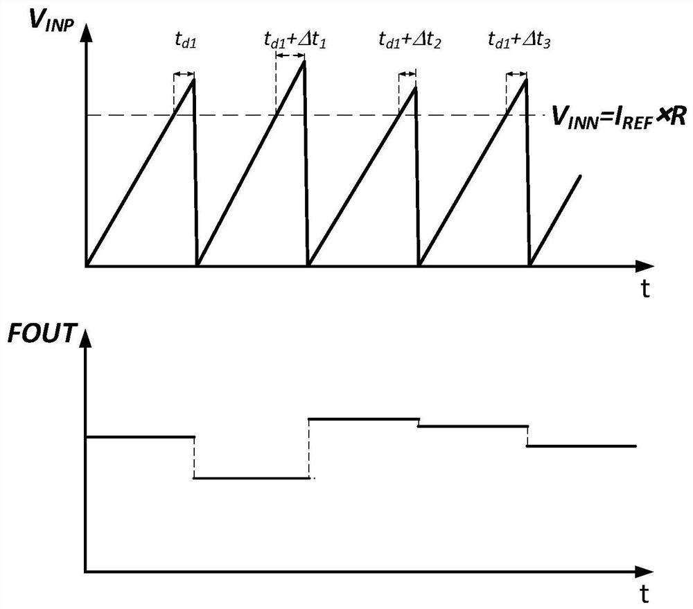
[0003] In the prior art, two identical reference current sources I REF , resistors, capacitors, comparators, buffers, and reset switches are used as a fully integrated clock, and the clock period generated by the RC oscillator is equal to the sum of RC delay, comparator delay, and buffer delay. In general, the comparison The value of the delay of the comparator and the delay of the buffer is relatively large, and the sum of the two will occupy more than 2% of a clock cycle. In addition, the delay of the comparator and the delay of the buffer will change greatly with the change of temperature and power supply voltage. Therefore, the current The stability of the clock frequency output by the RC oscillator in the prior art is poor

Method used


Image

  • Resistor-capacitor RC oscillator
  • Resistor-capacitor RC oscillator
  • Resistor-capacitor RC oscillator

Examples


Embodiment Construction

[0020] Embodiments of the present application will be described in detail below in conjunction with the accompanying drawings.

[0021] It should be clear that the described embodiments are only some of the embodiments of the present application, not all of the embodiments. Based on the embodiments in this application, all other embodiments obtained by persons of ordinary skill in the art without creative efforts fall within the protection scope of this application.

[0022] figure 1 is a schematic structural diagram of an RC oscillator in the prior art, figure 2 for with figure 1 corresponding to the timing diagram, the RC oscillator consists of two identical reference current sources I REF , resistors, capacitors, comparators, buffers and reset switches. The negative terminal voltage of the comparator V INN equal to I REF ×R, positive terminal voltage V INP equal to I REF The voltage obtained by charging the capacitor C. When the positive terminal voltage V INP gr...


PUM


Abstract

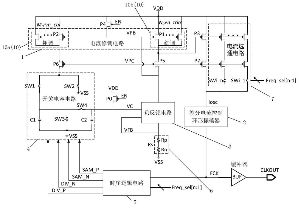
The embodiment of the invention discloses a resistance-capacitance RC oscillator, relates to the technical field of clocks, and aims to improve the stability of output clock frequency. The RC oscillator comprises a mirror current source, wherein a first end is connected with an oscillation part, a second end is connected with a negative feedback part and a third end is connected with a switched capacitor part; one end of the oscillation part is connected with the mirror current source, and the other end is connected with the sequential control part; one end of the sequential control part is connected with the oscillation part, and the other end is connected with the switched capacitor part; one end of the switched capacitor part is connected with the time sequence control part, the other end of the switched capacitor part is connected with the negative feedback part, the mirror current source is used for charging according to the control of the control pulse, and charges are transferred to the negative feedback part from the switched capacitor part; the input end of the negative feedback part is connected with the switched capacitor part, the feedback end is connected with the mirror current source through the feedback resistor, and the input voltage is equal to the feedback voltage through the negative feedback effect. The application is suitable for generating clocks.

Description

technical field [0001] The present application relates to the technical field of clocks, in particular to a resistor-capacitor RC oscillator. Background technique [0002] A stable clock source is one of the most important issues in the field of integrated circuits. Although a crystal oscillator can provide a very high-precision clock reference source, it has disadvantages such as high application cost, long start-up time, and inability to integrate on-chip. Therefore, the importance of fully integrated high-precision on-chip clock sources in SoC, MCU, high-speed interface and other application fields is becoming more and more prominent. [0003] In the prior art, two identical reference current sources I REF , resistors, capacitors, comparators, buffers, and reset switches are used as a fully integrated clock, and the clock period generated by the RC oscillator is equal to the sum of RC delay, comparator delay, and buffer delay. In general, the comparison The value of the...

Claims


Application Information

Patent Timeline
IPC IPC(8): H03K3/353
CPCH03K3/353
Inventor 张文龙
Owner HYGON INFORMATION TECH CO LTD
Learn More