Knotting mould for crucible and knotting method

A mold and crucible technology is applied in the field of crucible knotting molds and knotting, which can solve the problems of losing the quality of metallurgical ingots without considering the removal of water vapor, and the quality of the sintered inner wall is bad, so as to improve the quality, eliminate defects and hidden dangers, The effect of preventing transverse cracks in the crucible

Active Publication Date: 2021-04-09
西安聚能高温合金材料科技有限公司
View PDF6 Cites 0 Cited by
  • Summary
  • Abstract
  • Description
  • Claims
  • Application Information

AI Technical Summary

Problems solved by technology

[0002] In the process of knotting the crucible for ordinary high-temperature alloy vacuum induction furnace, the upper and lower parts of the crucible often use dry material of two kinds of materials. The thermal expansion and contraction near the furnace nozzle, and the alternating changes of cold and heat, so the crucible often produces transverse cracks at the furnace nozzle, that is, at the joint of the two materials; the design and production of the original crucible knotting mold did not consider the water vapor in the dry material Excluded, the quality of the sintered inner wall of the crucible is good and bad
When cracks appear on the inner wall of the induction furnace crucible or the sintering quality of the inner wall is not good, it is not only easy to wear steel and cause safety accidents, but also easy to drop slag and blocks at the cracks, which is not conducive to the improvement of the quality of metallurgical ingots

Method used


Image

  • Knotting mould for crucible and knotting method

Examples


Embodiment Construction

[0027] The present invention will be described in further detail below in conjunction with the accompanying drawings and embodiments.

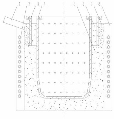
[0028] A crucible knotting mould, comprising an inner ring mold 4 and an outer ring mold 3, a furnace body wall 8 is arranged outside the inner ring mold 4, an outer ring mold 3 is arranged between the inner ring mold 4 and the furnace body wall 8, The space between the furnace body wall 8 and the inner ring mold 4 is filled with magnesium oxide dry shot 1 5; the space between the inner ring mold 4 and the outer ring mold 3 is filled with magnesium oxide dry shot 2 6; the outer ring The cavity between the mold 3 and the furnace body wall 8 is filled with a mixed dry hammering material 7 .

[0029] The outer ring mold 3 is a ring-shaped mold, the height of the outer ring mold 3 is one-third of the height of the inner ring mold 4, and the outer ring mold 3 is set at the outer top third of the inner ring mold 4. position, the outer ring mold 3 c...


PUM


Abstract

The invention discloses a knotting mould for a crucible. A furnace body wall is arranged on the outer part of an inner ring mould; an outer ring mould is arranged between the inner ring mould and the furnace body wall; the interior of a space which is formed between the furnace body wall and the inner ring mould is filled with a first magnesium oxide dry ramming material; a second magnesium oxide dry ramming material is filled between the inner ring mould and the outer ring mould; and the interior of a cavity body which is positioned between the outer ring mould and the furnace body wall is filled with a mixed dry ramming material. The knotting method comprises the following steps: 1), knotting the furnace bottom, adding the first magnesium oxide dry ramming material in batches, performing degassing and compacting by vibration, and scraping hairs; 2), knotting the furnace wall; 3), performing up-and-down vibration in corresponding positions of the inner ring mould by using a radial vibrator when material addition, compaction and knotting are carried out every three times; 4), ensuring that the space between the outer ring mould and the inner ring mould is equal uniformly; 5), filling the first magnesium oxide dry ramming material between the inner ring mould and the outer ring mould until the knotting operation is carried out completely and the first magnesium oxide dry ramming material arrives at the top of the furnace body wall; 6), performing sealing by using the mixed dry ramming material; and 7), taking out the outer ring mould and completing a knotting operation of the crucible. The knotting mould disclosed by the invention has the characteristics of preventing cracking, buffering high-temperature stress, and improving the anti-vibrating stability.

Description

technical field [0001] The invention belongs to the technical field of metallurgical casting, and in particular relates to a crucible knotting mold and a knotting method. Background technique [0002] In the process of knotting the crucible for ordinary high-temperature alloy vacuum induction furnace, the upper and lower parts of the crucible often use dry material of two kinds of materials. The thermal expansion and contraction near the furnace nozzle, and the alternating changes of cold and heat, so the crucible often produces transverse cracks at the furnace nozzle, that is, at the joint of the two materials; the design and production of the original crucible knotting mold did not consider the water vapor in the dry material Excluded, the quality of the crucible sintered inner wall is good and bad. When there are cracks on the inner wall of the induction furnace crucible or the sintering quality of the inner wall is not good, it is not only easy to wear steel and cause s...

Claims


Application Information

Patent Timeline
Patent Type & Authority Applications(China)
IPC IPC(8): F27B14/10
CPCF27B14/10F27B2014/102
Inventor 杨恩赵岐李会武付宝全刘利伟李创路杨天宇张茜张灿辰王盛交杨旭
Owner 西安聚能高温合金材料科技有限公司
Why Eureka
Try Eureka