Laser irradiation device and surface roughening method using same

A surface roughening and laser irradiation technology, which is applied in laser welding equipment, manufacturing tools, welding/welding/cutting items, etc., can solve problems such as sandpaper quality deviation, achieve the effect of reducing damage and avoiding peak current

Pending Publication Date: 2021-04-09
PHOENIX ELECTRIC CO
View PDF7 Cites 1 Cited by
  • Summary
  • Abstract
  • Description
  • Claims
  • Application Information

AI Technical Summary

Problems solved by technology

[0003] However, such methods have the following problems: the use of sandpaper has variations in quality due to contact, sandblasting has problems with the working environment due to dust, and water spray or chemical treatment requires drainage facilities.

Method used


Image

  • Laser irradiation device and surface roughening method using same
  • Laser irradiation device and surface roughening method using same
  • Laser irradiation device and surface roughening method using same

Examples


Deformed example 1

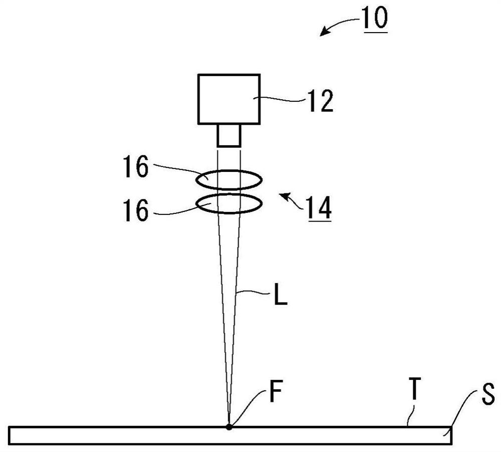
[0056]In the above embodiment, a laser irradiation apparatus 10 is constituted by a set of laser light source 12 and the collecting member 14, but a plurality of laser light sources 12 and a collecting member 14 may be combined to constitute a laser irradiation device 10.

[0057]Such asFigure 6 As shown, the laser irradiation apparatus 10 according to the modification 1 is composed of, for example, by combining 5 groups of laser light source 12 and the collecting member 14.

[0058]The focus position F of the laser light L light L-facing member S is set to a given interval, respectively, respectively, and each focus position F is arranged.

[0059]When such a laser irradiation apparatus 10 is integrally in the direction (hereinafter, referred to as "longitudinal") in the direction (hereinafter, referred to as "longitudinal"), and is called "longitudinal"). When irradiating the laser light L, ifFigure 7 As shown, the surface T of the component S can form a concave portion X in a checkerboard...

experiment example

[0061]In the case where the laser irradiation apparatus 10 is irradiated with the surface T of the CFRP material (component S) formed by substantially parallel to a large amount of carbon fibers, the diameter of each recessed portion X formed by each laser light L The interval size of the focus positions f between each laser light L is in the width direction, and the longitudinal interval size as a parameter, the preferred longitudinal interval size is confirmed. Further, the direction of the carbon fiber contained in the CFRP material (component S) is consistent with "longitudinal".

[0062]The component S is fixed, and the laser irradiation apparatus 10 is irradiated with a laser light L of the pulse-shaped waveform at a given time interval while moving on the longitudinal direction. Therefore, the surface shape of each of the recess X is a longitudinal longitudinal elliptical shape. Hereinafter, the length of the longitudinal direction in the surface shape of the concave portion X i...


PUM


Abstract

It is intended to provide a laser irradiation device, and a surface roughening method using the same, whereby it is made possible to irradiate a laser beam optimal to perform roughening treatment for the surface of a member in order to enhance adhesiveness on the surface of the member, and simultaneously, a laser diode, even when used as a light source of the laser beam, can be mitigated in damage. The present laser irradiation device (10) irradiates a laser beam (L) at intervals of predetermined time. At one time of irradiation, the laser beam (L) has a waveform composed of a former portion (100) and a latter portion (104). In the former portion (100), an increase rate of irradiation intensity per unit time is maximized on an outset of irradiation and is gradually reduced as the irradiation intensity approaches a maximum. In the latter portion (104), a reduction rate of irradiation intensity per unit time is maximized after the former portion (100) and is gradually reduced as the irradiation intensity approaches a baseline current.

Description

Technical field[0001]The present invention relates to a laser irradiation apparatus for enabling the surface of the member to increase the adhesiveness of the surface and a surface roughened treatment method using the laser irradiation device.Background technique[0002]When the adhesive is used to bond the member, the treatment of the surface roughening of the member is typically performed as a pretreatment. This "roughened" treatment is typically used, for example, a method of sandpaper, sandblasting, water spray, or chemical treatment.[0003]However, such a method has the following problems: the use of sandpaper uses the quality of the quality due to contact formation, the sandblasting there is a problem, water spray or chemical treatment of the work environment, water spray or chemical treatment.[0004]Therefore, in order to solve these problems, it is developed to suppress the deviation of quality by non-contact, and there is no problem with the work environment, and the roughening...

Claims


Application Information

Patent Timeline
Patent Type & Authority Applications(China)
IPC IPC(8): B23K26/356B23K26/70
CPCB23K26/3568B23K26/702B23K26/355B23K26/0622B23K26/3584B23K2103/16B23K26/0604B23K26/0648B23K26/0869
Inventor 乡田哲也渡边加名木下雅章
Owner PHOENIX ELECTRIC CO
Why Eureka
Try Eureka