Sensor calibration method, device, equipment, system and medium
A calibration method and sensor technology, applied in control/regulation systems, instruments, transportation and packaging, etc., can solve the problems of slow calibration speed, low calibration accuracy, and high labor costs, reduce labor costs, and improve calibration speed and calibration accuracy. , to avoid the effect of manual manual calibration
- Summary
- Abstract
- Description
- Claims
- Application Information
AI Technical Summary
Problems solved by technology
Method used
Image
Examples
Embodiment 1
[0034] figure 1 It is a schematic flow chart of a sensor calibration method provided by Embodiment 1 of the present invention. This embodiment is applicable to the scene of calibrating sensors on automatic driving vehicles produced on the production line. This method can be performed by a sensor calibration device. Can consist of hardware and / or software, and can be integrated into a calibration server. The method specifically includes the following:
[0035] S101. Control at least two unmanned guided vehicles to sequentially transport the vehicles to be calibrated to the calibration room.
[0036] Among them, the Automated Guided Vehicle (Automated Guided Vehicle) is also commonly referred to as the AGV trolley. AGV trolley refers to a transport vehicle that is equipped with automatic guidance devices such as electromagnetic or optical, can travel along the specified guidance path, has safety protection and various transfer functions, and is a transport vehicle that does no...
Embodiment 2
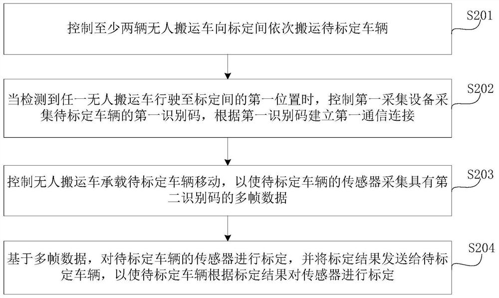
[0056] Figure 2A It is a schematic flowchart of a sensor calibration method provided by Embodiment 2 of the present invention. On the basis of the above embodiments, this embodiment further explains the calibration of the sensor of the vehicle to be calibrated based on the first communication connection. Such as Figure 2A As shown, the method specifically includes:
[0057] S201. Control at least two unmanned guided vehicles to successively transport the vehicles to be calibrated to the calibration room.
[0058] S202. When it is detected that any one of the unmanned guided vehicles travels to the first position in the calibration room, control the first collection device to collect the first identification code of the vehicle to be calibrated, and establish an identification code based on the first identification code. A first communication connection.
[0059] S203. Control the unmanned guided vehicle to carry the vehicle to be calibrated to move, so that the sensor of...
Embodiment 3
[0078] image 3 It is a schematic flowchart of a sensor calibration method provided by Embodiment 3 of the present invention. On the basis of the above embodiments, this embodiment further optimizes the control of at least two unmanned guided vehicles to sequentially transport the vehicles to be calibrated to the calibration room. Such as image 3 As shown, the method specifically includes:
[0079] S301. Control a first unmanned guided vehicle to transport a first vehicle to be calibrated to the calibration room, and control at least one second unmanned guided vehicle to transport a second vehicle to be calibrated to a waiting area of the calibration room.
[0080] Among them, the first unmanned guided vehicle refers to the first AGV car that carries the vehicle to be calibrated, or refers to the first AGV car that arrives at the calibration room;
[0081] Correspondingly, the second unmanned guided vehicle refers to other AGVs other than the first vehicle to be calibrat...
PUM
 Abstract
Description
Claims
Application Information
 - R&D Engineer
- R&D Manager
- IP Professional
- Industry Leading Data Capabilities
- Powerful AI technology
- Patent DNA Extraction
Browse by: Latest US Patents, China's latest patents, Technical Efficacy Thesaurus, Application Domain, Technology Topic, Popular Technical Reports.
© 2024 PatSnap. All rights reserved.Legal|Privacy policy|Modern Slavery Act Transparency Statement|Sitemap|About US| Contact US: help@patsnap.com


