Multi-dimensional Force Acquisition Method Based on Parallel Link Multi-dimensional Force Sensor
A technology of multi-dimensional force sensor and acquisition method, which is applied in the direction of measuring force components, measurement of property force using piezoelectric devices, instruments, etc., can solve the problems of small sensor structure stiffness, low multi-dimensional force accuracy, and complicated calculation process, etc. Achieve the effect of fast calculation speed, high calculation accuracy and high precision
- Summary
- Abstract
- Description
- Claims
- Application Information
AI Technical Summary
Problems solved by technology
Method used
Image
Examples
specific Embodiment approach 1
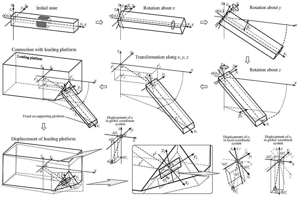
[0087] Parallel rod system multi-dimensional force sensor, such as figure 1 As shown, the support platform and the load platform are rigid bodies (in practical applications, both the support platform and the load platform are pseudo-rigid bodies, that is, approximate rigid bodies with minimal deformation), and the load platform and the support platform are connected by a parallel rod system (multiple strain beams) , the strain beam in the parallel bar system is used as the elastic sensitive element;
[0088] A micro-displacement measurement sensor is arranged between the support platform and the load platform to measure the micro-displacement between the two (caused by the deformation of the strain beam). The micro-displacement measurement sensor includes electrical, optical displacement sensors and other non-contact or micro-force contact sensors; electrical Displacement sensors generally use electrical sensors such as capacitance, inductance, and eddy current, and optical di...
specific Embodiment approach 2
[0094] Before describing this embodiment, the representation form of the space vector symbol of the present invention is firstly described, for example The whole of each parameter is described as a form;
[0095] The main body of the symbol represents a space vector, Q represents a generalized force including force and moment, F represents a force, and M represents a moment; Δ represents a generalized deformation including displacement and rotation angle deformation, ΔD represents displacement deformation, Δθ represents rotation angle deformation; r represents a strain beam The distance between the origin of the local coordinate system and the origin of the global coordinate system in the global coordinate system, β represents the rotation angle of the local coordinate system of the strain beam around the three axes of the global coordinate system;
[0096] The superscript on the upper left corner represents the coordinate system, the upper corner on the upper left corner i...
specific Embodiment approach 3
[0157] According to this embodiment, the micro-displacement of the load platform in six directions under the action of external force is measured by the micro-displacement measuring sensor arranged between the support platform and the load platform. The specific process is as follows:
[0158] The measurement of the displacement of the load platform can use a non-contact electrical displacement sensor or an optical displacement sensor or a micro-force contact displacement sensor:
[0159] As shown in Figure 9, Figure 9(a) is a capacitive sensor, only x j The displacement on the axis has an effect on the capacitive displacement sensor; Figure 9(b) is a triangular light sensor, and only x j The displacement on the axis has an effect on the triangular optical displacement sensor;
[0160] As shown in Figure 10(a) and Figure 10(b), the local coordinate system of the displacement sensor attached to the displacement sensor is established, and the displacement direction measured by ...
PUM
 Abstract
Description
Claims
Application Information
 - R&D
- Intellectual Property
- Life Sciences
- Materials
- Tech Scout
- Unparalleled Data Quality
- Higher Quality Content
- 60% Fewer Hallucinations
Browse by: Latest US Patents, China's latest patents, Technical Efficacy Thesaurus, Application Domain, Technology Topic, Popular Technical Reports.
© 2025 PatSnap. All rights reserved.Legal|Privacy policy|Modern Slavery Act Transparency Statement|Sitemap|About US| Contact US: help@patsnap.com


