
Current limiter, compressor and air conditioner

A current limiter and current limiting technology, applied in the direction of machine/engine, mechanical equipment, high-efficiency adjustment technology, etc., can solve the imbalance of centrifugal inertia force of single eccentric block, affect the lubrication effect of compressor parts, and easily generate vibration and noise, etc. problem, to achieve the effect of good automatic adjustment, clever design, and long service life

Active Publication Date: 2021-04-06
ZHUHAI GREE REFRIGERATION TECH CENT OF ENERGY SAVING & ENVIRONMENTAL PROTECTION
View PDF8 Cites 0 Cited by
  • Summary
  • Abstract
  • Description
  • Claims
  • Application Information

AI Technical Summary

Problems solved by technology

However, in the patent application for this invention, the oil supply of the compressor in the low-frequency state is not controlled, which may easily lead to insufficient oil supply when the compressor is running at low frequency, which will affect the lubrication effect of the compressor parts; in addition, Opening holes on the crankshaft will reduce the strength of the crankshaft, and the centrifugal inertial force of the single eccentric block is unbalanced, which is prone to vibration and noise

Method used


Image

  • Current limiter, compressor and air conditioner
  • Current limiter, compressor and air conditioner
  • Current limiter, compressor and air conditioner

Examples


Embodiment 1

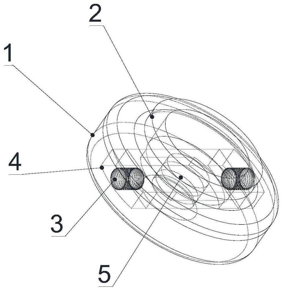
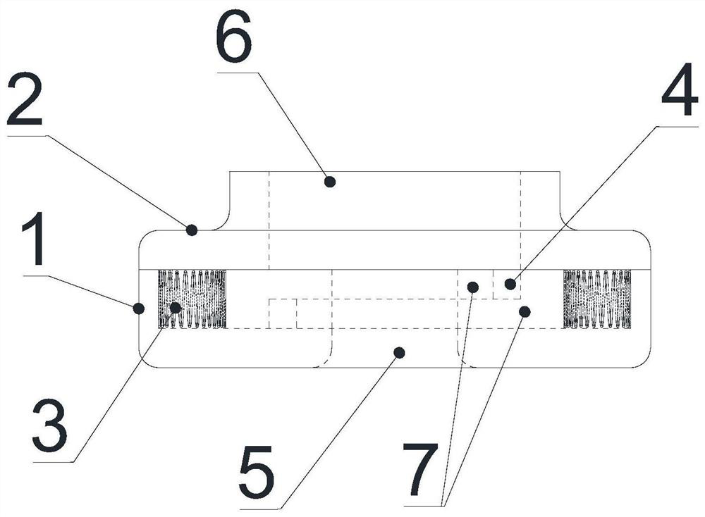
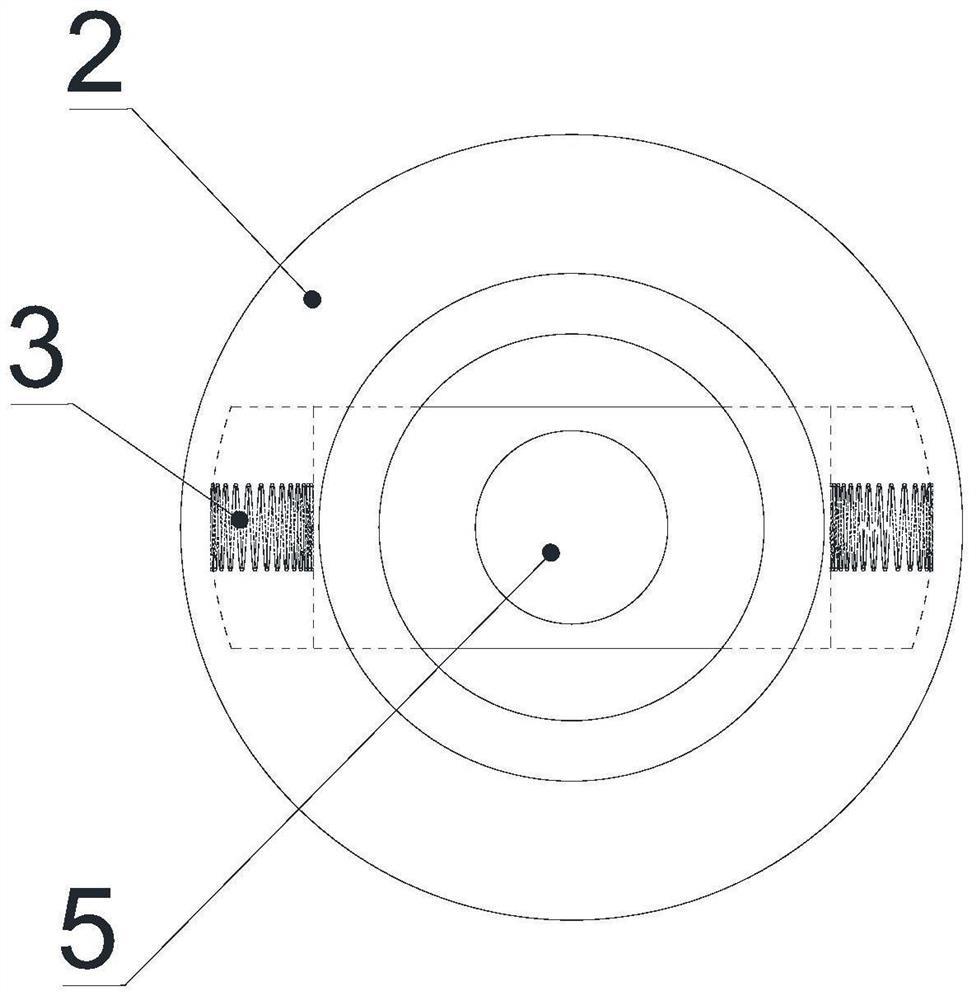
[0031] see Figure 1-Figure 6 , the flow limiter of this embodiment includes a seat body and a sliding flow limiting assembly; wherein, an oil inlet channel 5 is provided in the center of the inner cavity of the seat body, and the oil inlet channel 5 is arranged through the seat body along the axial direction; the compressor The lower end of the crankshaft is connected to the top of the seat body, and the central oil passage of the crankshaft communicates with the oil inlet passage 5;

[0032] The sliding current limiting assembly includes two sliding current limiting parts 7, the two sliding current limiting parts 7 are oppositely arranged in the inner cavity of the seat, and the two sliding current limiting parts 7 are superimposed on each other; the two sliding current limiting parts Elastic elements 3 are provided between the part 7 and the inner cavity wall of the seat, and transition holes 11 are provided on the two sliding flow limiting parts 7; when the compressor is i...

Embodiment 2

[0046] The difference between this embodiment and Embodiment 1 is that the inner wall of the connection hole 6 on the flow limiting cap is provided with a threaded structure. In this way, the lower end of the crankshaft and the flow limiting cap can be connected through a threaded structure, making disassembly and assembly more convenient.


PUM


Abstract

The invention discloses a current limiter, a compressor and an air conditioner. The current limiter comprises a seat body and a sliding current limiting assembly. An oil inlet channel is formed in the center of an inner cavity of the seat body and penetrates through the seat body in the axial direction. The lower end of a crankshaft of the compressor is connected with the top of the seat body, and a central oil channel of the crankshaft communicates with the oil inlet channel. The sliding current limiting assembly comprises two sliding current limiting pieces, the two sliding current limiting pieces are oppositely arranged in the inner cavity of the seat body, and the two sliding current limiting pieces overlap each other. Elastic elements are arranged between the two sliding current limiting pieces and the inner cavity wall of the seat body, and transition holes are formed in the two sliding current limiting pieces. According to the current limiter, oil supply control of the compressor at high frequency and low frequency can be achieved at the same time, and the adaptability is good.

Description

technical field [0001] The invention relates to the technical field of compressor equipment, in particular to a flow limiter, a compressor and an air conditioner. Background technique [0002] At present, room air conditioners generally use vertical rolling rotor compressors, and the loss of mechanical efficiency accounts for about 20% of the power loss. A good lubrication system is an important measure to reduce the mechanical loss of the compressor and reduce the wear of parts. Vertical rolling rotor compressors generally have a pressure differential oil supply structure. Common practices include opening an oil hole in the center of the crankshaft and adding oil guides and flow limiters. However, the current compressor lubrication system is designed according to the rated frequency, resulting in compressor failure. Insufficient oil supply at low frequency and increased oil supply at high frequency, resulting in adverse effects such as increased oil content in the exhaust. ...

Claims


Application Information

Patent Timeline
Patent Type & Authority Applications(China)
IPC IPC(8): F04C29/02
CPCF04C29/021Y02B30/70
Inventor 李伟陈可余风利郭丽丽廖熠
Owner ZHUHAI GREE REFRIGERATION TECH CENT OF ENERGY SAVING & ENVIRONMENTAL PROTECTION
Learn More