
Movable type ground wire box

A mobile, ground wire technology, applied in the directions of internal accessories and external accessories, can solve the problems of high labor intensity, time-consuming and laborious operation, low work efficiency, etc., and achieve the effect of reducing labor intensity, flexible and convenient operation, and convenient access.

Inactive Publication Date: 2017-08-29
STATE GRID SHANDONG ELECTRIC POWER COMPANY WEIFANG POWER SUPPLY +1
View PDF5 Cites 1 Cited by
  • Summary
  • Abstract
  • Description
  • Claims
  • Application Information

AI Technical Summary

Problems solved by technology

When storing, the staff usually stuffs the bundled ground wires into the storage slot at will. At least two ground wires are placed in each slot until the entire storage slot is filled. When taking it, it is easy to cause the two ground wires to be entangled
With this kind of placement slot structure, the grounding wire can only be taken and placed by dragging, and the grounding wire will rub against the cabinet body seriously, which will easily cause the insulation layer of the grounding wire to be damaged.
In addition, this kind of safety tool cabinet takes up a lot of space and the number of wiring that can be placed is limited
[0004] In addition to the above problems, multiple sets of grounding wires are often used in a power operation and maintenance or maintenance operation, which requires the staff to go back and forth between the tool cabinet and the work vehicle. The line is removed from the tool cabinet, and then lifted to the work vehicle with the help of a trailer or two people, and then lifted up and sent into the work vehicle, the operation is time-consuming, labor-intensive, and low-efficiency

Method used


Image

  • Movable type ground wire box
  • Movable type ground wire box
  • Movable type ground wire box

Examples


Embodiment Construction

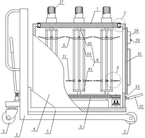
[0030]Referring to the accompanying drawings, the movable ground box of the present invention includes an L-shaped underframe 1, the bottom of the underframe 1 is provided with rollers 2, and the underframe 1 is equipped with a lifting base 3 driven by a hydraulic mechanism located at its rear. , the lifting base 3 is provided with a box body 4, and the front portion of the box body 4 is provided with an opening and a box door 41 is installed on the opening. A turntable 5 is mounted on the bottom of the box body 4, and the bottom of one side wall of the box body 4 is rotated to be equipped with a transverse transmission shaft 17. The extended end of the ratchet sleeve 30 is connected with a pedal 32, the pedal 32 is connected with an extension spring 33, and the top of the extension spring 33 is connected on the outer side wall of the casing. A plurality of vertically arranged turrets 6 are installed at intervals on the circumference of the top surface of the turntable 5 , the...


PUM


Abstract

The invention relates to a movable type ground wire box. The movable type ground wire box comprises a bottom frame; a lifting base is arranged on the bottom frame; a box body is arranged on the lifting base; a rotating table is rotationally arranged at the bottom of the box body; a transverse transmission shaft is rotationally arranged at the bottom of the box body in a penetrating mode; the rotating table is in power connection with the inner extending end of the transverse transmission shaft through a gear transmission mechanism; the outer extending end of the transverse transmission shaft is connected with a ratchet wheel sleeve; a pedal is connected to the ratchet wheel sleeve; a tension spring is connected to the pedal; the top end of the tension spring is connected to the outer side wall of the box body; a plurality of rotating frames which are vertically arranged are arranged on the top surface of the rotating table; the top ends of the rotating frames are connected to a disc, and the disc is rotationally connected to the top wall of the box body; the rotating frames each comprise a base plate, a top plate and supporting rods; annular hanging frames are fixedly arranged at the tops of the rotating frames; a plurality of upper hanging rods are annularly arranged on the annular hanging frames; and the bottoms of the supporting rods are provided with lower hanging rods in a sliding mode. The movable type ground wire box has the advantages that the structure is simple, the control is flexible and convenient, the labor intensity of workers can be greatly reduced, and the working efficiency can be improved.

Description

technical field [0001] The invention relates to the field of electrical safety tools, in particular to a movable ground box. Background technique [0002] High-voltage grounding wire is a commonly used safety tool in power production. Its function is to prevent personal injury accidents caused by accidental voltage on equipment and lines that have been powered off during the construction of lines and substations. As an obvious grounding point for equipment maintenance, grounding wires are used very frequently in power system work. Therefore, in addition to the structure and correct installation of the grounding wire itself must meet the safety regulations for power equipment maintenance, the storage and retrieval of the grounding wire must also be done. Very important. [0003] At present, the access of the grounding wire in the substation basically uses a safety tool cabinet, which is a common cabinet structure, and the cabinet body is divided into multiple placement slots...

Claims


Application Information

Patent Timeline
IPC IPC(8): B65D25/24B65D25/02B65D25/20
CPCB65D25/02B65D25/20B65D25/24
Inventor 孙炜春李玉志吴金玉晋飞刘晓亮王娟娟温国强刘贯红曹春刚黄海丽王鹤飞赵斌财黄学增金峰唐敏邱韵如孙守鑫卢绍强杨君仁朱海南
Owner STATE GRID SHANDONG ELECTRIC POWER COMPANY WEIFANG POWER SUPPLY
Learn More