
Section steel packaging device

A technology of section steel and machine base, applied in the field of packaging equipment, can solve the problems of high labor intensity, low packaging production efficiency, cumbersome manual operation process, etc., to facilitate loading and unloading, ensure stability, and improve reliability Effect

Active Publication Date: 2021-04-06
天津市兴盛泰钢结构有限公司
View PDF8 Cites 0 Cited by
  • Summary
  • Abstract
  • Description
  • Claims
  • Application Information

AI Technical Summary

Problems solved by technology

[0003] When the C-shaped steel is stacked up and down neatly, the C-shaped steel needs to be packaged with a steel belt. In the prior art, the steel belt is manually wound on the outside of the C-shaped steel, and the wrapped steel belt is manually tightened. After the belt is tightened, the steel belt buckle is used to press and clamp the C-shaped steel through the packing clamp to prevent the loosening of the C-shaped steel. However, due to the cumbersome manual operation process and the high labor intensity of the staff, the packing production efficiency is low.

Method used


Image

  • Section steel packaging device
  • Section steel packaging device
  • Section steel packaging device

Examples


Embodiment Construction

[0036] The present invention will be clearly and completely described below in conjunction with the embodiments.

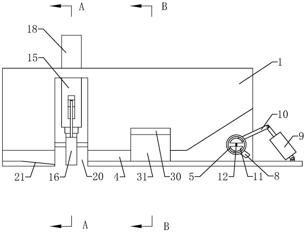
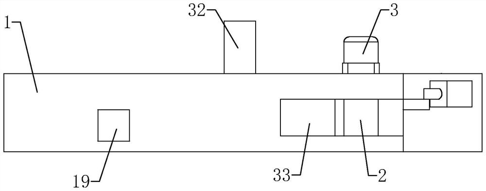
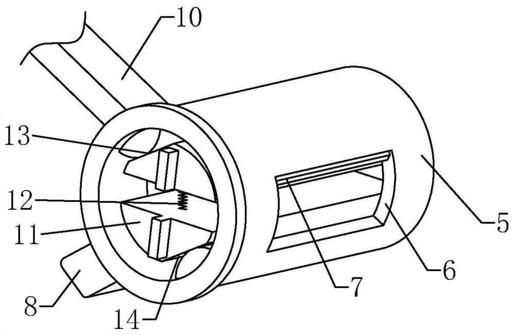
[0037] See attached figure 1 And attached figure 2, a section steel packaging device, comprising a machine base 1, one end of the upper length direction of the machine base 1 is formed with a material guide groove 33, and the bottom surface of the material guide groove 33 is along the length direction of the machine base 1 from the middle of the top surface of the machine base 1 toward the end of the machine base 1 Facing the slope inclined downwards, the upper part of the machine base 1 is rotated and provided with two oppositely rotating rolls 2, and the two rolls 2 are all arranged in the material guide groove 33, and a motor 3 is fixed on one side of the machine base 1 in the width direction, and the extended end of the motor 3 is extended. It enters the inside of the machine base 1 and is coaxially fixed with the upper roll 2; the lower part of the machine ...


PUM


Abstract

The invention discloses a section steel packaging device, and relates to the technical field of packaging equipment. The section steel packaging device comprises a machine base, two oppositely rotating rollers are rotatably arranged at the upper part of the machine base, a motor for driving one of the rollers to rotate is fixed on the machine base, a belt passing channel is formed below the machine base, a locking and cutting mechanism is arranged at the position, close to the upper part of the feeding side, of the belt passing channel, and a buckling mechanism is arranged at the upper portion of the discharging side of the belt passing channel. The locking and cutting operation of a steel belt is completed through the locking and cutting mechanism, the buckling operation of the steel belt is completed through the buckling mechanism, and therefore, the operation process of workers is simplified. The section steel packaging device is convenient and reliable to use and improved in packaging efficiency.

Description

technical field [0001] The invention relates to the technical field of packaging equipment, in particular to a section steel packaging device. Background technique [0002] C-shaped steel is a cold-rolled profile with a C-shaped cross-section. It has a thin wall, light weight, excellent performance, and high strength. It is mainly used in the construction field. At present, C-shaped steel is automatically processed and formed by a C-shaped steel forming machine, and an assembly line has been formed. Production, after it is made and shaped, it is generally necessary to stack and pack C-shaped steel. [0003] When the C-shaped steel is stacked up and down neatly, the C-shaped steel needs to be packaged with a steel belt. In the prior art, the steel belt is manually wound on the outside of the C-shaped steel, and the wrapped steel belt is manually tightened. After the belt is tightened, it is pressed and clamped with a steel belt buckle by the packing clamp to prevent the loos...

Claims


Application Information

Patent Timeline
IPC IPC(8): B65B11/02B65B41/10B65B51/10B65B61/06
CPCB65B11/02B65B51/10B65B41/10B65B61/06
Inventor 刘玉亮
Owner 天津市兴盛泰钢结构有限公司
Learn More