A kind of manufacturing method of chamfered can

A manufacturing method and chamfering technology, which can be applied to household appliances, hollow objects, other household appliances, etc., can solve the problems of poor chamfering and stuck products, and achieve the effect of qualified performance, avoiding overheating of rubber, and uniform rubber layer.

Active Publication Date: 2022-07-12
广东昊达智能装备科技有限公司
View PDF3 Cites 0 Cited by
  • Summary
  • Abstract
  • Description
  • Claims
  • Application Information

AI Technical Summary

Problems solved by technology

[0007] However, the rubber layer of the tank can create dimples that can get caught in the product, resulting in poor chamfering, requiring picking and rework to be arranged

Method used

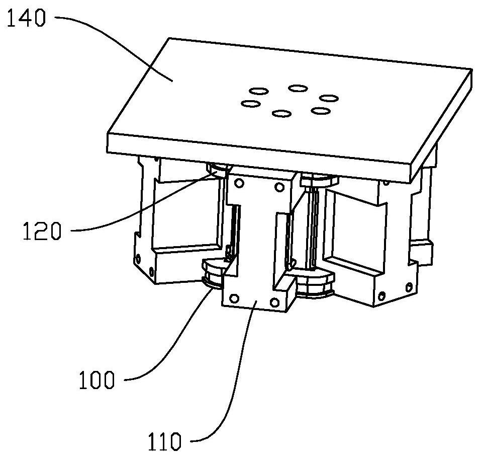
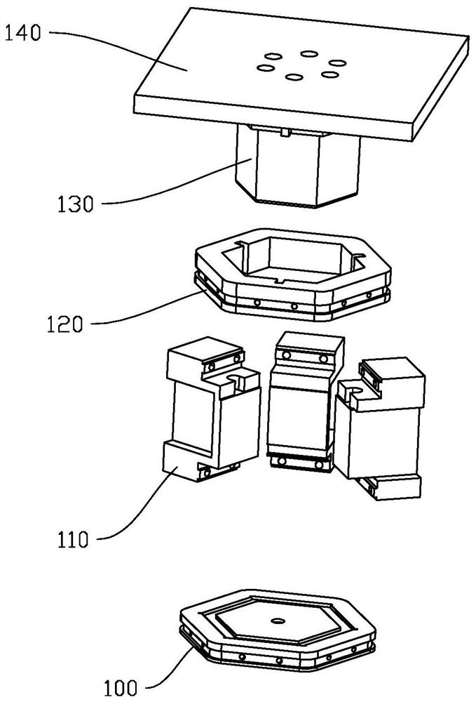

Image

  • A kind of manufacturing method of chamfered can
  • A kind of manufacturing method of chamfered can
  • A kind of manufacturing method of chamfered can

Examples


Embodiment Construction

[0031] This part will describe the specific embodiments of the present invention in detail, and the preferred embodiments of the present invention are shown in the accompanying drawings. Each technical feature and overall technical solution of the invention should not be construed as limiting the protection scope of the invention.

[0032] In the description of the present invention, it should be understood that the azimuth description, such as the azimuth or position relationship indicated by up, down, front, rear, left, right, etc., is based on the azimuth or position relationship shown in the drawings, only In order to facilitate the description of the present invention and simplify the description, it is not indicated or implied that the indicated device or element must have a particular orientation, be constructed and operated in a particular orientation, and therefore should not be construed as limiting the present invention.

[0033] In the description of the present in...


PUM

PropertyMeasurementUnit
hardnessaaaaaaaaaa

Abstract

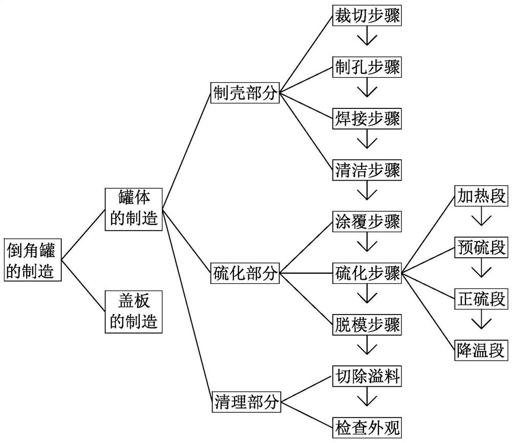
The invention discloses a manufacturing method of a chamfered tank, comprising: a shell-making part of the tank body: manufacturing a metal shell of the tank body, and the surface of the metal shell is clean; the vulcanization part of the tank body: filling the metal shell with glue Vulcanization, including a coating step, a vulcanization step, and a mold release step, wherein the coating step coats the inner surface of the metal shell with an adhesive, the vulcanization step uses a vulcanizer and a vulcanization mold, and the vulcanization step The metal shell is filled with rubber and vulcanized. The vulcanization step includes a preheating section, a pre-vulcanizing section, a positive sulfur section, a cooling section and a demoulding section; the cleaning part of the tank body: remove the vulcanization flash to obtain the tank body. The manufacturing method of the chamfered can of the present invention can reduce or even prevent the occurrence of pits in the rubber layer of the can body, avoid poor chamfering, and save the cost of picking and rework.

Description

technical field [0001] The invention relates to the manufacture of chamfered cans, in particular to a manufacturing method of a chamfered can. Background technique [0002] The applicant is committed to the research and development of chamfering technology. At present, he has developed and applied for a patent for a chamfering machine. The patent number of the chamfering machine is CN201821383350.0, and the patent name of the chamfering machine is a chip electronic component. Chamfering machine. At the same time, among the key components of the chamfering machine, a patent for a chamfering tank has also been applied. The patent number of the chamfering tank is CN201821379162.0, and the patent name of the chamfering tank is an electronic component chamfering tank. [0003] In the above-mentioned chamfered can, the chamfered can has a can body and a cover plate. [0004] When using, put multiple products and grinding liquid into the tank, then close the tank with a cover pla...

Claims


Application Information

Patent Timeline
Patent Type & Authority Patents(China)
IPC IPC(8): B29D22/00B23P15/00B29C63/48B29C35/02
CPCB29D22/003B23P15/00B29C63/48B29C35/0288
Inventor 赖斌贤严波龙清明徐能旺邓江宾李毅孔德祐
Owner 广东昊达智能装备科技有限公司
Why Eureka
Try Eureka