PFNA short intramedullary nail

A technique of intramedullary nailing, short type, applied in PFNA short type intramedullary. It can solve the problems of low matching degree of femoral medullary cavity, impact or extrusion, and postoperative pain of patients, so as to improve the convenience of operation, avoid stress concentration and reduce postoperative pain.

Pending Publication Date: 2021-04-06
BEIJING CHUNLIZHENGDA MEDICAL INSTR
View PDF3 Cites 0 Cited by
  • Summary
  • Abstract
  • Description
  • Claims
  • Application Information

AI Technical Summary

Problems solved by technology

[0003] The current standard type of PFNA intramedullary nail is on the coronal plane, the distal and proximal ends have 6° valgus, and the sagittal plane is linear, but the human femur has a certain valgus angle on the coronal plane. There is a certain anterior arch on the sagittal plane. Since the distal end of the main intramedullary nail has no anterior arch, after it is implanted into the proximal femur, the degree of matching with the femoral medullary cavity is low, and the tip of the distal end of the main nail is likely to hit the femoral cortex. Thereby causing postoperative pain in patients, which is not conducive to the recovery of patients
Due to the mismatch between the main nail and the femoral medullary cavity, the distal end of the main nail squeezes the femoral cortex, resulting in stress concentration, which increases the risk of postoperative main nail breakage or passing through the femoral cortex
[0004] Therefore, there is an urgent need for a short PFNA intramedullary nail, which can better fit the medullary cavity after being implanted in the femoral medullary cavity, and solve the problem of impact or extrusion of the distal end of the intramedullary nail because the main nail of the intramedullary nail has no anterior arch. Medullary cavity, resulting in stress concentration of the intramedullary nail after implantation into the femoral medullary cavity, passing through the cortical bone, hitting the cortical bone with the nail tip, and causing pain to the patient

Method used


Image

  • PFNA short intramedullary nail
  • PFNA short intramedullary nail
  • PFNA short intramedullary nail

Examples


Embodiment Construction

[0022] In order for those skilled in the art to better understand the technical solution of the present invention, a short intramedullary PFNA with anterior arch of the present invention will be further described in detail below in conjunction with the drawings and specific embodiments.

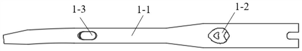
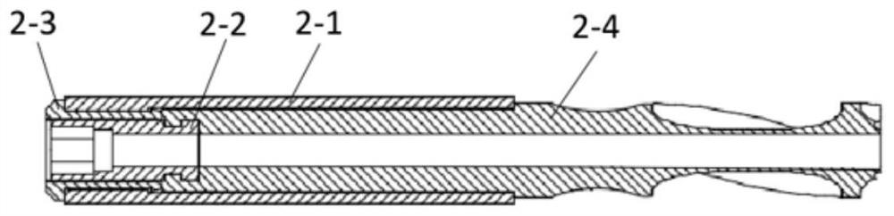
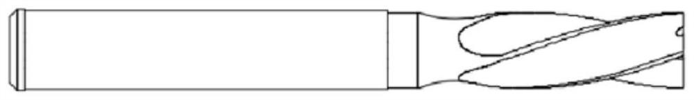
[0023] A short intramedullary PFNA with a forward arch, comprising a hollow main nail 1, a helical blade 2, a horizontal locking nail, and a tail nail, and the bolt blade 2, the horizontal locking nail, and the tail nail are detachably connected to the main nail, The proximal end and the distal end of the main nail have a certain angle of abduction and bending, and the distal end of the main nail 1 has a certain forward arc on the sagittal plane, and the proximal end, the distal end and the tail of the main nail 1 are respectively Locking screw holes are provided, wherein the bolt blades, horizontal locking nails, and tail nails are mated with the locking screw holes on the main nail. The spi...


PUM


Abstract

The invention provides a PFNA short type intramedullary nail which comprises a hollow main nail, a spiral blade, a lock nail and a tail nail, the bolt blade, the transverse lock nail and the tail nail are detachably connected with the main nail, the near end and the far end of the main nail have abduction bending of a certain angle, and the far end of the main nail has a certain anterior arch radian on a sagittal plane. The anterior arch radian design of the far end of the main nail on the sagittal plane is added, so that the main nail is more tightly attached to the femoral medullary cavity, in practical application, the femoral anatomical form is optimally matched, the operation convenience of the intramedullary nail is improved, stress concentration caused by mismatching of the intramedullary nail and the femoral medullary cavity can be avoided, and postoperative pain of a patient is reduced. Re-fracture caused by the fact that the nail point impacts the cortical bone or penetrates out of the cortical bone is effectively prevented.

Description

technical field [0001] The invention relates to a medical device, in particular to a short type intramedullary PFNA with anterior arch curvature. Background technique [0002] PFNA intramedullary nail, femoral interlocking intramedullary nail, is a widely used fracture intramedullary fixation device, which includes a long rod component main nail implanted in the femoral medullary cavity of the patient, implanted from the femoral cortex to the femoral neck and The proximal locking part of the femoral head is the helical blade, the distal femoral interlocking part is the interlocking screw and the end part of the main nail is the tail nail. Moreover, the main nail has a certain anatomical radian. For long tubular femoral fractures, the intramedullary nail is more in line with the biomechanical characteristics of the femur. The proximal end of the main nail is provided with oblique locking perforations, and the distal end is provided with one or two transverse locking perforat...

Claims


Application Information

Patent Timeline
IPC IPC(8): A61B17/72A61B17/76
CPCA61B17/725A61B17/744
Inventor 李正戎史春宝郭静王振国岳术同
Owner BEIJING CHUNLIZHENGDA MEDICAL INSTR
Why Eureka
Try Eureka