
A rotary drilling rig electric control cabinet device and installation method

A technology of rotary drilling rig and electric control cabinet is applied in the automatic control system of drilling, mechanical equipment, earth-moving drilling, etc., which can solve problems such as high temperature failure, and achieve the effect of reducing the temperature rise of the environment and having strong practicability.

Active Publication Date: 2022-05-27
CHTC JOVE HEAVY IND
View PDF5 Cites 0 Cited by
  • Summary
  • Abstract
  • Description
  • Claims
  • Application Information

AI Technical Summary

Problems solved by technology

[0006] The object of the present invention is to provide an electric control cabinet device for a rotary drilling rig, to solve the problems caused by the high temperature failure of the components in the electric control cabinet body during the construction of the rotary drilling rig in the prior art, and to further protect the The stability and reliability of the rotary drilling rig is also a good protection for the performance and life of various electrical components in the electric control cabinet of the rotary drilling rig.

Method used


Image

  • A rotary drilling rig electric control cabinet device and installation method
  • A rotary drilling rig electric control cabinet device and installation method
  • A rotary drilling rig electric control cabinet device and installation method

Examples


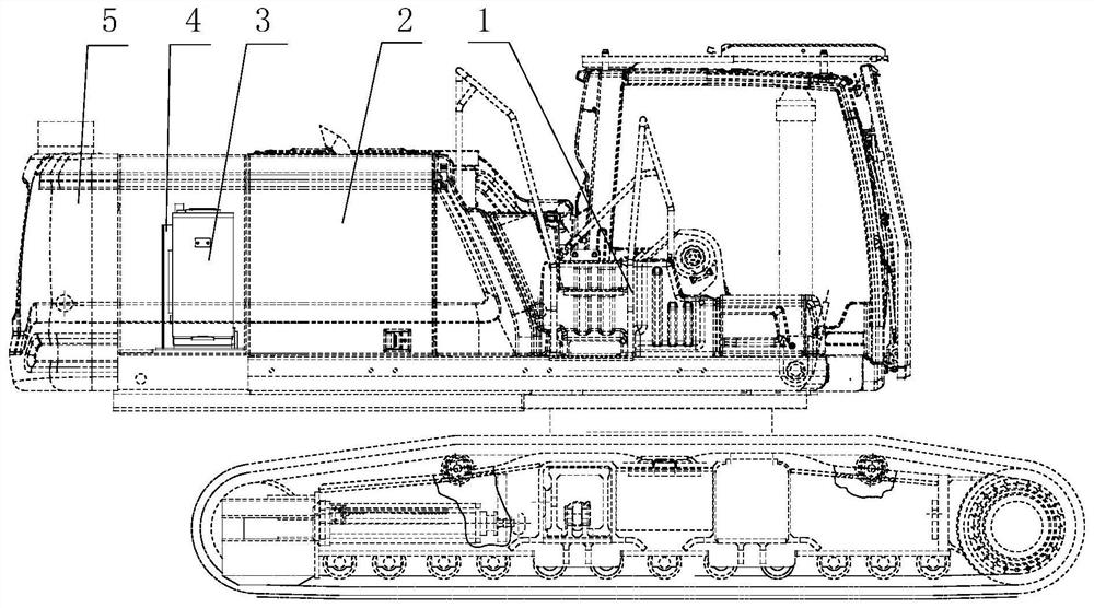
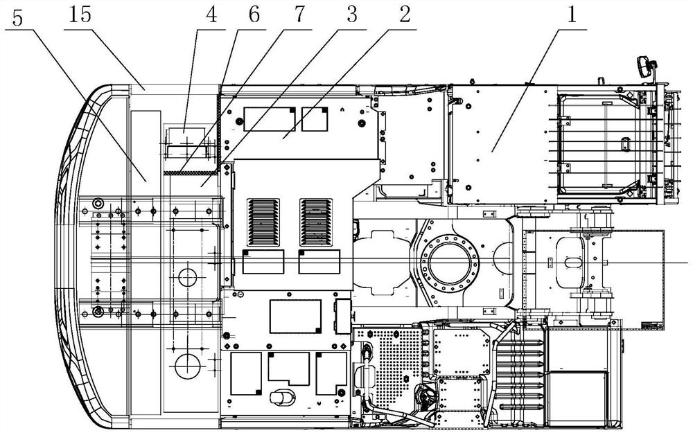
Embodiment Construction

[0026] The embodiments of the present invention will be described in detail below with reference to the accompanying drawings, but the present invention may be implemented in many different ways as defined and covered by the claims.

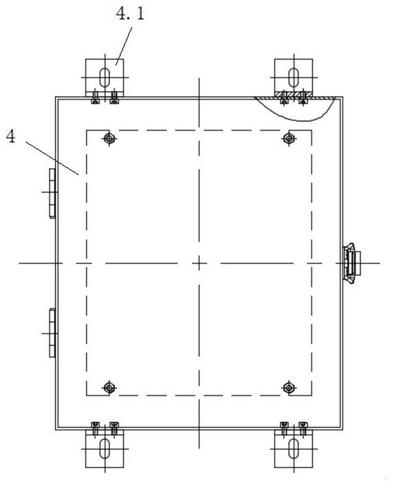
[0027] See Figure 1 to Figure 4 , This embodiment provides an electric control cabinet device for a rotary drilling rig, which includes an electric control cabinet main body 4, a heat insulation device and an air-cooled heat dissipation system. The specific structure is as follows:

[0028] The main body 4 of the electric control cabinet is arranged on the main engine 1 of the rotary drilling rig and between the engine 2, the auxiliary hydraulic oil tank 3 and the counterweight assembly 5; wherein, the cooling system of the auxiliary hydraulic oil tank 3 and the engine 2 is to affect the electric control cabinet of the present invention. The main heat source for the normal use of electrical components in the body; the counterweight assembly 5 i...


PUM


Abstract

The invention discloses an electric control cabinet device of a rotary drilling rig and an installation method thereof. The electric control cabinet device includes a main body of the electric control cabinet, a heat insulation device and an air-cooled heat dissipation system; , between the auxiliary hydraulic oil tank and the counterweight assembly; the engine faces the main body of the electric control cabinet and the auxiliary hydraulic oil tank faces the main body of the electric control cabinet, and respectively installs heat-insulating sponges to block the heat of the engine and the auxiliary hydraulic oil tank on the components of the electric control cabinet. At the same time, it also reduces the temperature rise of the surrounding environment of the electric control cabinet caused by the mutual radiation between the engine and the auxiliary hydraulic oil tank; a cooling fan and a temperature sensor are installed in the main body of the electric control cabinet, and the temperature signal sensed by the temperature sensor is directly transmitted to the rotary Drilling rig controller and rotary drilling rig controller can control the speed of the cooling fan according to the actual temperature, effectively protecting the performance and life of various electrical components in the main body of the electric control cabinet, and reducing construction costs.

Description

technical field [0001] The invention relates to the technical field of piling machinery, in particular, to an electric control cabinet device and an installation method whose electric control components are easy to fail due to a rotary drilling rig constructed in a high temperature environment for a long time. Background technique [0002] The rotary drilling rig is a kind of hydraulic drive equipment, which drives the rotation and pressure of the drill pipe and the drill bucket by controlling the rotation and pressure of the power head to cut the soil into the drill bucket, and then rely on the lifting of the main winch wire to lift the drill pipe. The bucket is brought out of the hole, and then the drill bucket is brought to the position deviated from the hole by the rotary action of the rotary drilling rig, and the bucket door of the drill bucket is opened by the soil thrower of the power head to discharge the soil out of the hole. Periodic operation equipment. In the con...

Claims


Application Information

Patent Timeline
Patent Type & Authority Patents(China)
IPC IPC(8): H05K7/20F02B77/13F02B77/11E21B44/00
CPCH05K7/20136H05K7/20181H05K7/20145E21B44/00F02B77/11F02B77/13
Inventor 湛良传黎起富罗瑶吴江苏熊浩陈浩
Owner CHTC JOVE HEAVY IND
Learn More