
Portable pressure test pump

A pressure test pump and portable technology, applied in the field of portable pressure test pumps, can solve problems such as the lag of safety inspection technical means, achieve good social benefits and economic value, be easy to carry, and avoid the effects of excessive pressure

Pending Publication Date: 2021-04-02
中国人民解放军火箭军工程大学
View PDF0 Cites 0 Cited by
  • Summary
  • Abstract
  • Description
  • Claims
  • Application Information

AI Technical Summary

Problems solved by technology

[0009] Aiming at the problems in the prior art, the present invention provides a portable pressure test pump, which can not only solve the problems of lagging safety inspection technical means during the inspection and maintenance of pressure vessels, but also can be promoted to other industries, which can greatly improve Improve the safety technology level of related equipment in the whole society, and provide technical support to ensure the absolute safety of pressure vessel equipment and prevent major safety accidents

Method used


Image

  • Portable pressure test pump
  • Portable pressure test pump
  • Portable pressure test pump

Examples


no. 1 example

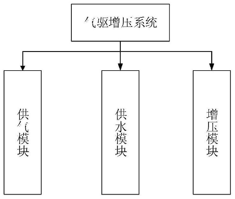
[0042] A portable pressure test pump, comprising an electronic scale, a water tank is fixedly connected to the top of the electronic scale, a supercharger is movably connected inside the water tank, and a first pressure gauge is fixedly connected to one side of the supercharger. A first manual switch, a throttle valve, and a solenoid valve are fixedly installed sequentially between the supercharger and the pressure gauge, and a second manual switch is fixedly connected to one side of the solenoid valve, and the second manual switch One end of the relay is fixedly connected with a relay and a timer in turn, and a pressure sensor is movably connected to one side of the relay. The solenoid valve, timer and pressure sensor belong to the pressure detection system, and one end of the pressure sensor is fixedly connected with an intelligent digital display meter. , one end of the electromagnetic valve is fixedly connected to a computer, and the control system is composed of the pressu...

no. 2 example

[0044] Portable pressure vessel safety inspection device solid model and physical picture Figure 7 shown. The shape, size, layout, operation method, etc. are the same as the actual equipment. Simplify the structure and processing technology under the premise of satisfying various operations.

[0045] 3. The third embodiment:

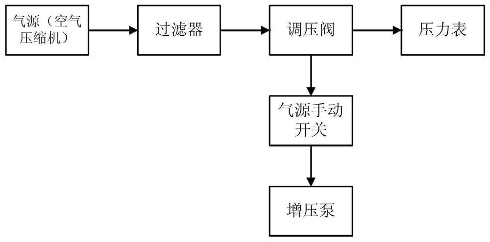
[0046] Such as Figure 9 As shown, when the equipment starts to work, turn on the power switch and gas manual switch, about 0.8MPa of pure air enters the pressurized cylinder through the air circuit, and obtains a high-pressure liquid output of up to about 80MPa after boosting. By adjusting the throttle valve to change the gas flow and then change the liquid flow, to achieve the purpose of changing the pressure test speed. The first pressure gauge and the second pressure gauge display driving gas and test pressure respectively. The pressure sensor is used to detect the experimental pressure. When it reaches the preset value, it will send a signal t...


PUM


Abstract

The invention relates to the technical field of water conservancy projects, in particular to a portable pressure test pump, which comprises a gas-driven pressurization, pressure detection and controlsystem, and is characterized in that the gas-driven pressurization technology adopts the working principle of Pascal's law, and the working area of driving gas and the area of a pressurized medium cylinder body is used for forming a ratio of the drive gas pressure to the pressure of the pressurized medium. According to the invention, the problems of lagging of safety inspection technical means andthe like in the detection and maintenance process of the pressure vessel can be solved, the safety technical level of related equipment can be greatly improved, technical support is provided for ensuring absolute safety of the pressure vessel and preventing major safety accidents, improvement of the safety state of the dispersedly configured pressure vessel is effectively promoted, and good social benefits and economic values are realized.

Description

technical field [0001] The invention relates to the technical field of hydraulic engineering, in particular to a portable pressure test pump. Background technique [0002] For a long time, the pressure vessel inspection institute has conducted safety inspections on these pressure vessels that require regular inspections. However, due to the huge number of pressure vessels required in the actual project, the annual regular inspection is a very huge project, and it is inevitable that there will be pressure vessels that are overdue or sick. These pressure vessels that are overdue or sick can be said to be The landmines with extremely destructive power buried under the road of social and economic construction and development in our country, if these "landmines" are not removed, there will be serious safety hazards, which not only endanger people's lives, but also greatly It affects the safety of other production equipment, and then affects the development of social economy. At...

Claims


Application Information

Patent Timeline
IPC IPC(8): G01N3/12G01N3/02
CPCG01N3/02G01N3/12
Inventor 秦忠宝刘琦邹子杰王鑫峰郭剑锋陶思昊
Owner 中国人民解放军火箭军工程大学
Learn More