
Integrated AIP assembly, terminal device and terminal device shell

A technology for terminal equipment and components, applied in the field of electronic information, can solve the problems of reduced scanning angle, increased return loss, poor versatility, etc., to achieve the effect of simple design process, enhanced scanning ability, and simple structure

Inactive Publication Date: 2021-03-30
XI AN JIAOTONG UNIV
View PDF12 Cites 0 Cited by
  • Summary
  • Abstract
  • Description
  • Claims
  • Application Information

AI Technical Summary

Problems solved by technology

[0005] Aiming at the technical problems existing in the prior art, the present invention provides an integrated AIP component, a terminal device and a terminal device casing to solve the problem that the millimeter wave array antenna in the prior art is easily affected by the device casing, resulting in an increase in its return loss , the gain is reduced, the scanning angle is reduced, and the technical problems of poor versatility

Method used


Image

  • Integrated AIP assembly, terminal device and terminal device shell
  • Integrated AIP assembly, terminal device and terminal device shell
  • Integrated AIP assembly, terminal device and terminal device shell

Examples


Embodiment 1

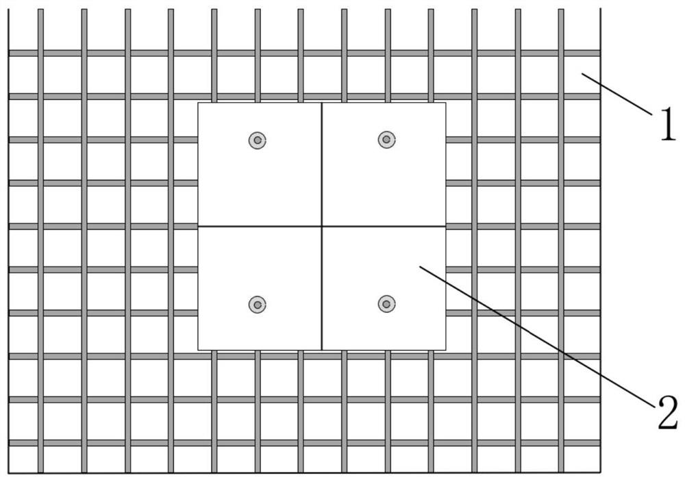
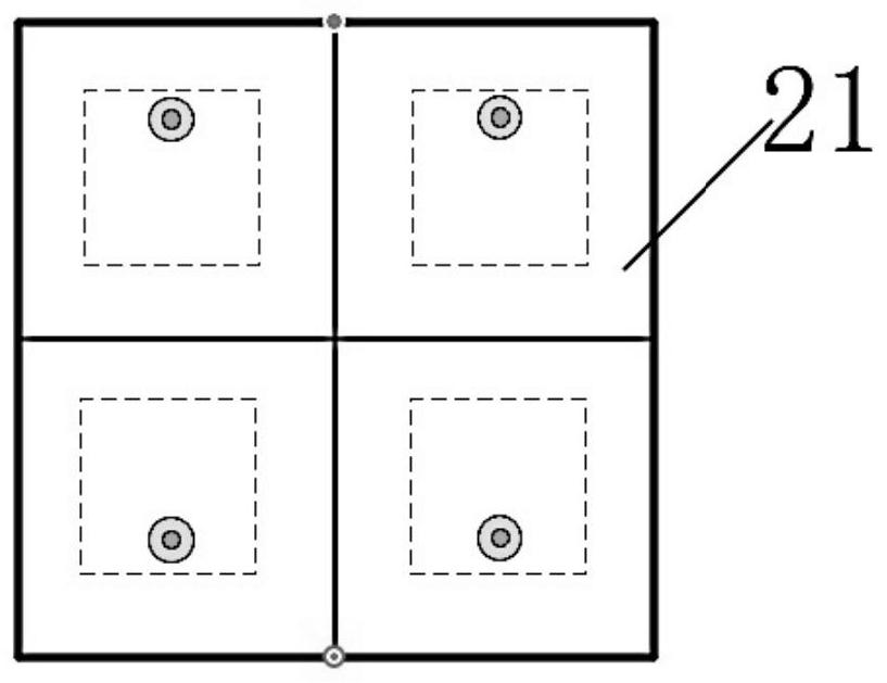
[0058] as attached Figure 1-9 As shown, this embodiment 1 provides an integrated AIP component, including a metamaterial structure 1 and an AIP component body 2, the metamaterial structure 1 is arranged above the AIP component body 2 at intervals, and between the metamaterial structure 1 and the AIP component body 2 The distance is 0.2-1.0mm, and it is set close to the side of the AIP component body; the metamaterial structure 1 adopts a metal structure layer, and the metal structure layer is set on the surface of the device casing 3, and is set close to the side of the AIP component body 2; a metal structure is provided The equivalent dielectric constant of the device casing 3 of the layer matches that of vacuum; the equivalent dielectric constant of the device casing 3 provided with the metal structure layer is 1-3.

[0059] The metal structure layer is arranged on the surface of the device casing 3 by coating or spraying process. The metal structure layer includes metal st...

Embodiment 2

[0068] as attached Figure 13 As shown, the structure and design principles of Embodiment 2 and Embodiment 1 are basically the same, the difference is that the metal structural unit 11 adopts a square patch structure, and the square patch structure is periodically arranged on the surface of the device casing 3 .

Embodiment 3

[0070] as attached Figure 14 As shown, the structure and design principles of Embodiment 3 and Embodiment 1 are basically the same, the difference is that the metal structure unit 11 adopts a rectangular ring metal structure, and the rectangular ring metal structure is periodically arranged on the surface of the device casing 3 .


PUM

PropertyMeasurementUnit
widthaaaaaaaaaa
thicknessaaaaaaaaaa
relative permittivityaaaaaaaaaa

Abstract

The invention discloses an integrated AIP assembly, a terminal device and a terminal device shell, the integrated AIP assembly comprises metamaterial structures and an AIP assembly body, and the metamaterial structures are arranged above the AIP assembly body at intervals; the metamaterial structures adopt a metal structure layer, and the metal structure layer is arranged on the surface of the device shell and is arranged close to one side of the AIP assembly body; the equivalent dielectric constant of the device shell provided with the metal structure layer is matched with the dielectric constant of vacuum; the metamaterial structures are arranged above the AIP assembly body at intervals, the electromagnetic metamaterial theory is utilized, the equivalent dielectric constant of the deviceshell is reduced, it is ensured that the performance of the AIP assembly body in the device equipment is close to the performance of the AIP assembly body in a free space, and the effects of performance compensation of the AIP assembly body and approximate transparency of antenna radiation are achieved; the matching performance of the antenna in a working frequency band and the normal gain of theantenna in a free space are effectively recovered, the scanning angle of the antenna is improved, the universality of the integrated AIP assembly is effectively improved, and the design and manufacturing process is simple.

Description

technical field [0001] The invention belongs to the technical field of electronic information, and in particular relates to an integrated AIP component, a terminal device and a shell of the terminal device. Background technique [0002] In 5G terminal equipment, millimeter-wave antennas have become a significant development trend; and because in millimeter-wave frequency bands, antennas need to use high gain and adjustable beams to resist greater propagation loss compared with sub-6GHz frequency bands, millimeter-wave The wave antenna must be designed in the form of an active array; considering the precision control and cost requirements of mass production, it is currently a popular solution to use common integrated AIP (Antenna-in-Package) components in different types of terminal equipment. [0003] Due to the needs of terminal industrial design, the materials of the equipment shells in different types of terminal equipment are very different, such as glass, ceramics and e...

Claims


Application Information

Patent Timeline
Patent Type & Authority Applications(China)
IPC IPC(8): H01Q1/24H01Q1/36H01Q1/38H01Q1/48
CPCH01Q1/36H01Q1/38H01Q1/48H01Q1/243
Inventor 闫森郑颜刘文东
Owner XI AN JIAOTONG UNIV
Learn More