


Quick Research
Generate reliable direction feasibility study reports for your R&D in just a few steps.

Technical Q&A
Discover and master advanced knowledge NOW. Basics, ideas, possibilities, all at once.

Find Solutions
As an expert in R&D theories, this can generate solutions to your technical problems instantly.

Evaluate Feasibility
Analyze your overall solution with one click, know your potential R&D risks in advance.

Monitor Landscape
Get weekly tech updates, stay abreast of the latest tech innovations and key insights.
Reactor pressure stability control device and method
A pressure stabilization and control device technology, applied in the direction of fluid pressure control, electric fluid pressure control, control/regulation system, etc., can solve the problem of unable to stably control the pressure in the reactor, achieve good drying and dust removal effect, and improve the product Quality, improve the effect of sealing performance
- Summary
- Abstract
- Description
- Claims
- Application Information
AI Technical Summary
Problems solved by technology
Method used
Image

Examples
Embodiment 1
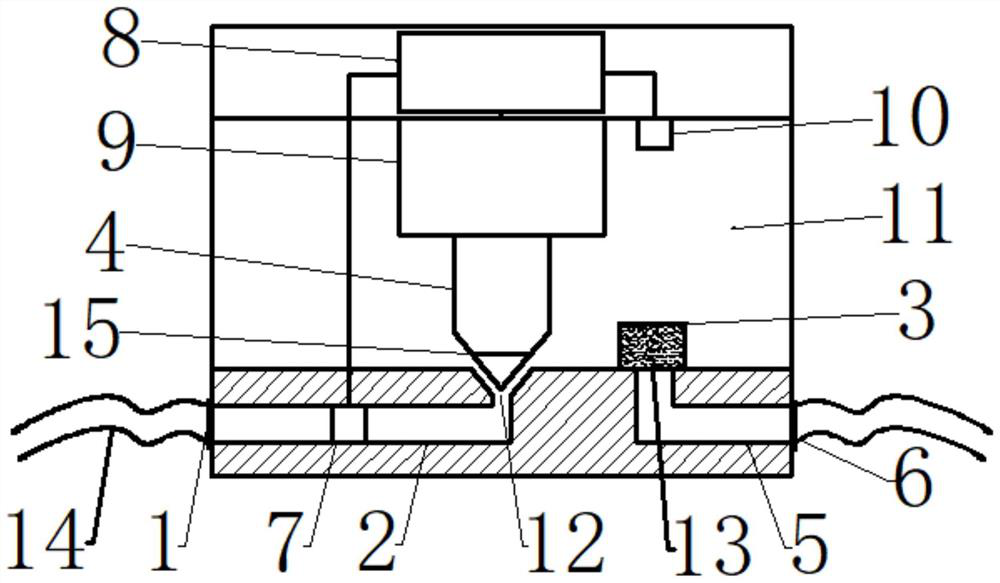
[0053] A reactor pressure stabilization control device, comprising an air inlet pipeline 2, an air chamber 11, a PLC controller 8 and a driving device 9, the air chamber 11 is provided with an air inlet 12, and the air inlet 12 is connected to the air inlet pipe 2, the driving device 9 is connected with a thimble 4, and the thimble 4 cooperates with the air inlet 12, and the air inlet pipe 2 is provided with a first pressure sensor 7, and the first pressure sensor 7 is connected with the PLC controller 8 is connected, the PLC controller 8 is connected with the driving device 9, and the air chamber 11 is also provided with an air outlet 13, and the air outlet 13 is communicated with the exhaust pipe 5, and the PLC controller 8 is externally connected with a main console, The PLC controller 8 is connected to the main console through WIFI signals. When the reactor starts feeding, the main console sends instructions to the pressure stabilization control device through WIFI, and the...
Embodiment 2
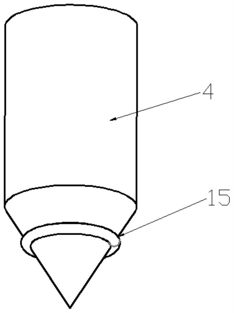
[0069] Embodiment two: the length of the tapered bus bar at the end of the thimble is 40mm, and the length of the conical surface of the air inlet 12 is 20mm. The inner wall surface of the thimble is set as a conical surface capable of forming a sealing surface with the outer wall surface of the thimble 4. Preferably, the length of the sealing surface along the direction of the generatrix of the conical surface is 20mm, which is not easy to cause sticking of the sealing surface, and the sealing effect is better. In addition, The corners at the end of the conical surface of the air inlet 12 are rounded, and the angle of the lower section of the air inlet 12 is rounded to avoid possible damage to the outside of the thimble 4 when the thimble 4 is inserted into the air inlet 12 from above by using a non-rounded structure. The problem of causing damage to the wall surface and thereby breaking the seal occurs.
Embodiment 3
[0070] Embodiment three: described air outlet 13 is provided with dry dust remover 3, and dry dust remover 4 comprises porous particulate matter, and described porous particulate matter can comprise activated carbon, zeolite molecular sieve and activated alumina, and this scheme preferably activated carbon, activated carbon is to airborne Water vapor and low-priced titanium dust have a good adsorption function, which can effectively prevent the gas from being condensed and mixed with the powder when it encounters air, which will cause the blockage of the exhaust pipe.
PUM
 Abstract
Description
Claims
Application Information
 - R&D Engineer
- R&D Manager
- IP Professional
- Industry Leading Data Capabilities
- Powerful AI technology
- Patent DNA Extraction
Browse by: Latest US Patents, China's latest patents, Technical Efficacy Thesaurus, Application Domain, Technology Topic, Popular Technical Reports.
© 2024 PatSnap. All rights reserved.Legal|Privacy policy|Modern Slavery Act Transparency Statement|Sitemap|About US| Contact US: help@patsnap.com