Automatic lens identifying and clamping device

An automatic identification and lens technology, applied in the field of optical communication, can solve problems such as low clamping efficiency, low clamping accuracy, and long time consumption, and achieve the effect of improving processing efficiency and high degree of automation

Pending Publication Date: 2021-03-30
CENT SOUTH UNIV
View PDF6 Cites 0 Cited by
  • Summary
  • Abstract
  • Description
  • Claims
  • Application Information

AI Technical Summary

Problems solved by technology

[0002] The lens is an extremely important optical component, which is used to refract light in a certain order. The lens needs to be coupled and installed in the corresponding product. The coupling accuracy will directly affect the quality of the corresponding product; the existing Most of the lenses of optical products adopt manual coupling or semi-automatic coupling. Among them, manual coupling requires the operator to set the optical path of the product in advance, and then use the equipment to set the lens on the optical path. Through subtle adjustments, the beam is refracted to achieve the desired effect. After determining the coupling position, it is necessary to fix the lens on the carrier through colloid. The whole process is cumbersome and time-consuming, and it is necessary to ensure that the lens will not be polluted or damaged during the whole process, otherwise it will easily affect the quality of optical products. In the process of manual operation, the clamping of the lens in semi-automatic coupling usually adopts a single clamping method such as clamping or air suction, which has low clamping efficiency and low clamping accuracy. In order to adapt to the single clamping method, it is usually necessary It is necessary to transfer the lens from the original tray to the special tray for clamping, which greatly increases the coupling time and reduces the coupling efficiency

Method used


Image

  • Automatic lens identifying and clamping device
  • Automatic lens identifying and clamping device
  • Automatic lens identifying and clamping device

Examples


Embodiment Construction

[0023] In order to make the technical problems, technical solutions and advantages to be solved by the present invention clearer, the following will describe in detail with reference to the drawings and specific embodiments.

[0024] The present invention provides an automatic lens identification and clamping device aiming at the problems of low efficiency, long time consumption and easily affected product quality in the existing lens clamping and coupling mode.

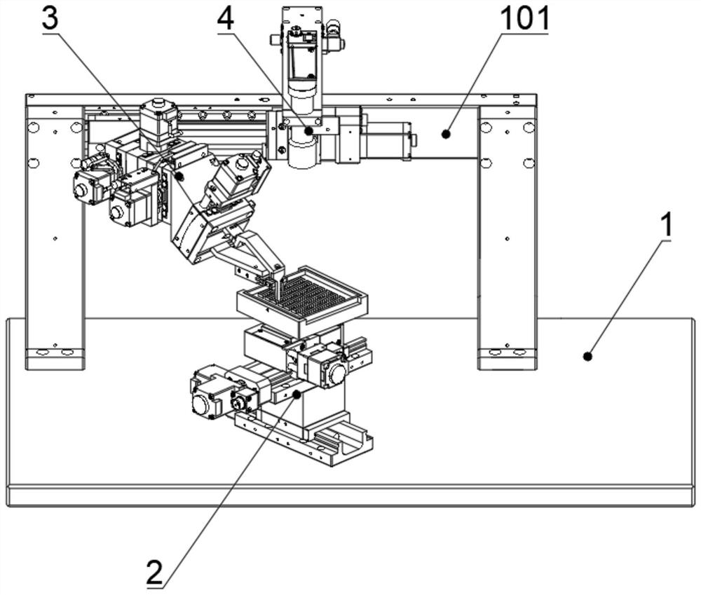
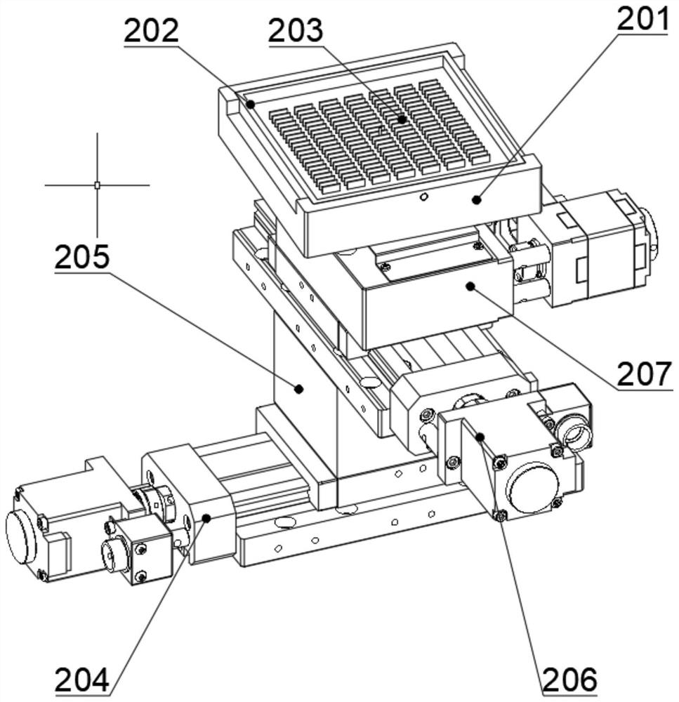
[0025] Such as Figure 1 to Figure 5 As shown, the embodiment of the present invention provides an automatic lens identification and clamping device, including: a device base plate 1, the device base plate 1 is arranged on a plane, and a beam 101 is arranged on the device base plate 1; a tray unit 2, The tray unit 2 is provided with a tray moving mechanism and a tray mounting seat 201, and the tray installation seat 201 is arranged on the bottom plate 1 of the device through the tray moving mechanism, and the tray mo...


PUM


Abstract

The invention provides an automatic lens identifying and clamping device. The automatic lens identifying and clamping device comprises a device bottom plate, a material disc unit, a clamp unit and a visual monitoring unit, wherein the device bottom plate is horizontally arranged, and a cross beam is arranged on the device bottom plate; the material disc unit is provided with a material disc movement mechanism and a material disc mounting seat, the material mounting seat is arranged on the device bottom plate through the material disc movement mechanism, and the material mounting seat is used for mounting a lens material disc; the clamp unit is provided with a clamp movement mechanism and a clamp mechanism, the clamp mechanism is arranged on the cross beam through the clamp movement mechanism, and the clamp unit is used for clamping and transporting a lens; and the visual monitoring unit is provided with a monitoring camera and a camera movement mechanism, and the monitoring camera is mounted on the cross beam through the camera movement mechanism. The automatic lens identifying and clamping device is high in automation degree, clamping, transporting and free coupling of the lens can be achieved, and the optical product machining efficiency and the optical product production quality are greatly improved.

Description

technical field [0001] The invention relates to the technical field of optical communication, in particular to an automatic lens identification and clamping device. Background technique [0002] The lens is an extremely important optical component, which is used to refract light in a certain order. The lens needs to be coupled and installed in the corresponding product. The coupling accuracy will directly affect the quality of the corresponding product; the existing Most of the lenses of optical products adopt manual coupling or semi-automatic coupling. Among them, manual coupling requires the operator to set the optical path of the product in advance, and then use the equipment to set the lens on the optical path. Through subtle adjustments, the beam is refracted to achieve the desired effect. After determining the coupling position, it is necessary to fix the lens on the carrier through colloid. The whole process is cumbersome and time-consuming, and it is necessary to ens...

Claims


Application Information

Patent Timeline
IPC IPC(8): B65G47/90
CPCB65G47/90
Inventor 段吉安马著唐佳卢胜强徐聪
Owner CENT SOUTH UNIV
Why Eureka
Try Eureka