A self-adjusting amplifier, its control method, and a multi-stage operational amplifier
An amplifier and self-zeroing technology, applied in amplifiers, differential amplifiers, DC-coupled DC amplifiers, etc., can solve problems such as output voltage burrs, ripples, and amplifier output voltage jumps, and reduce output burrs and ripples Effect
- Summary
- Abstract
- Description
- Claims
- Application Information
AI Technical Summary
Problems solved by technology
Method used
Image


Examples
Embodiment 1
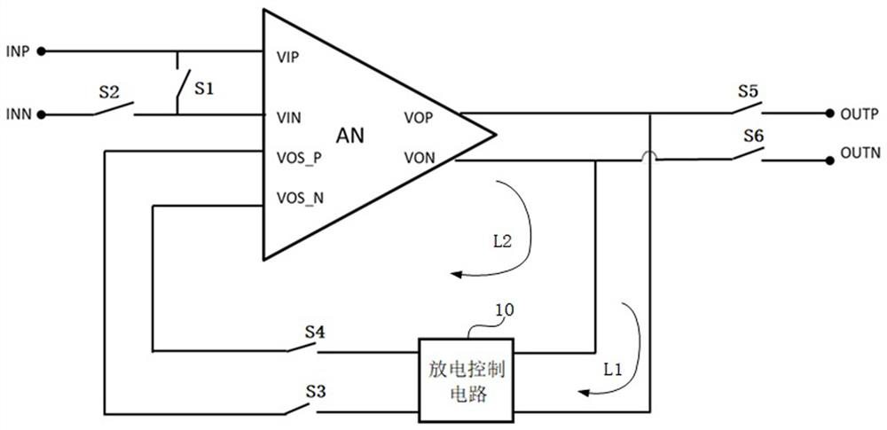
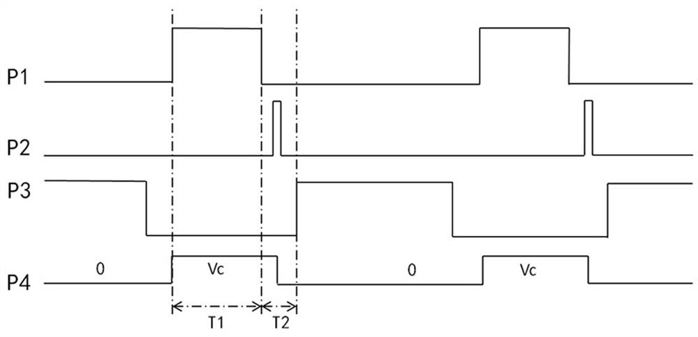
[0030] figure 1 It is a structural schematic diagram of a self-adjusting amplifier provided in Embodiment 1 of the present invention, figure 2 It is a schematic diagram of timing control of the self-adjusting amplifier provided in Embodiment 1 of the present invention. refer to figure 1 , a self-adjusting amplifier, characterized in that it includes: an amplification module AN, and the amplification module AN includes a first input terminal VIP, a second input terminal VIN, a third input terminal VOS_P, a fourth input terminal VOS_N, a first output terminal VOP and The second output terminal VON;
[0031] A first switch S1 connected in parallel between the first input terminal VIP and the second input terminal VIN; a second switch S2 connected in parallel with the second input terminal VIN; connected between the third input terminal VOS_P and the first output terminal VOP The third switch S3; the fourth switch S4 connected between the fourth input terminal VOS_N and the se...
Embodiment 2
[0038] image 3 It is a structural schematic diagram of an auto-zero amplifier provided in Embodiment 2 of the present invention. On the basis of the first embodiment above, optionally, refer to image 3 , the discharge control circuit 10 includes a discharge switch S0 connected between the first output terminal VOP and the second output terminal VON.
[0039] Specifically, after the amplifying module AN exits the self-adjusting state and before entering the amplifying state, control the first switch S1, the second switch S2, the third switch S3, the fourth switch S4, the fifth switch S5 and the sixth switch S6 to close turn off, control the discharge switch S0 to be turned on, and the discharge switch S0 is turned on so that the first output terminal VOP and the second output terminal VON of the amplification module AN are short-circuited, so that the first output terminal VOP and the second output terminal VON of the amplification module AN The voltage difference between t...
Embodiment 3
[0054] Figure 5 It is a structural schematic diagram of a multi-stage operational amplifier with self-adjusting function provided in Embodiment 3 of the present invention. On the basis of the above embodiments, optionally, refer to Figure 5 , including the main amplifier , adder 30, and two auto-zeroing amplifiers, such as Figure 5 in the first auto-zero amplifier 101 and the second auto-zero amplifier 102; where the first input of each auto-zero amplifier is connected to the main amplifier The first input terminal of each auto-zero amplifier is electrically connected to the second input terminal of the main amplifier The second input end of each auto-zeroing amplifier is electrically connected to the first input end of the adder 30, and the second output end of each auto-zeroing amplifier is electrically connected to the second input end of the adder 30. terminal connection, main amplifier The first output terminal of is electrically connected with the third input ...
PUM
 Abstract
Description
Claims
Application Information
 - R&D
- Intellectual Property
- Life Sciences
- Materials
- Tech Scout
- Unparalleled Data Quality
- Higher Quality Content
- 60% Fewer Hallucinations
Browse by: Latest US Patents, China's latest patents, Technical Efficacy Thesaurus, Application Domain, Technology Topic, Popular Technical Reports.
© 2025 PatSnap. All rights reserved.Legal|Privacy policy|Modern Slavery Act Transparency Statement|Sitemap|About US| Contact US: help@patsnap.com