
Protection device of electric power metering equipment

A protective device and power metering technology, which is applied in substation/power distribution device casing, cooling/ventilation of substation/switchgear, details of substation/switch layout, etc., can solve the problem of reducing the service life of power metering equipment, damage to power metering equipment, There are no problems such as good anti-high temperature function, so as to achieve the effect of good anti-high temperature and low temperature, improve efficiency, and facilitate disassembly and assembly

Pending Publication Date: 2021-03-26
GUANGDONG POWER GRID CORP ZHAOQING POWER SUPPLY BUREAU
View PDF7 Cites 1 Cited by
  • Summary
  • Abstract
  • Description
  • Claims
  • Application Information

AI Technical Summary

Problems solved by technology

[0003] In real life, the protection peripherals of power metering equipment have played a great role in power metering equipment, but the existing protection devices for power metering equipment on the market have certain shortcomings. For example, the announcement number is CN211266127U, and the announcement date is 2020.8.14 The Chinese patent - a protective peripheral device for power metering equipment, which only installs a protective plate on the outside of the power metering device, but the device does not have a good anti-high temperature function, so that when it is working, high temperature is generated, resulting in power metering Damage to equipment reduces the service life of power metering equipment

Method used


Image

  • Protection device of electric power metering equipment
  • Protection device of electric power metering equipment
  • Protection device of electric power metering equipment

Examples


Embodiment 1

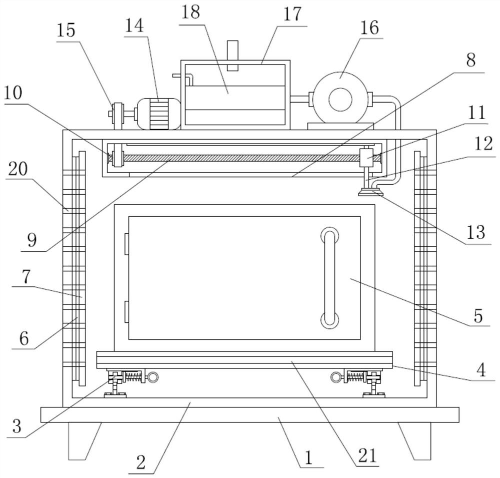
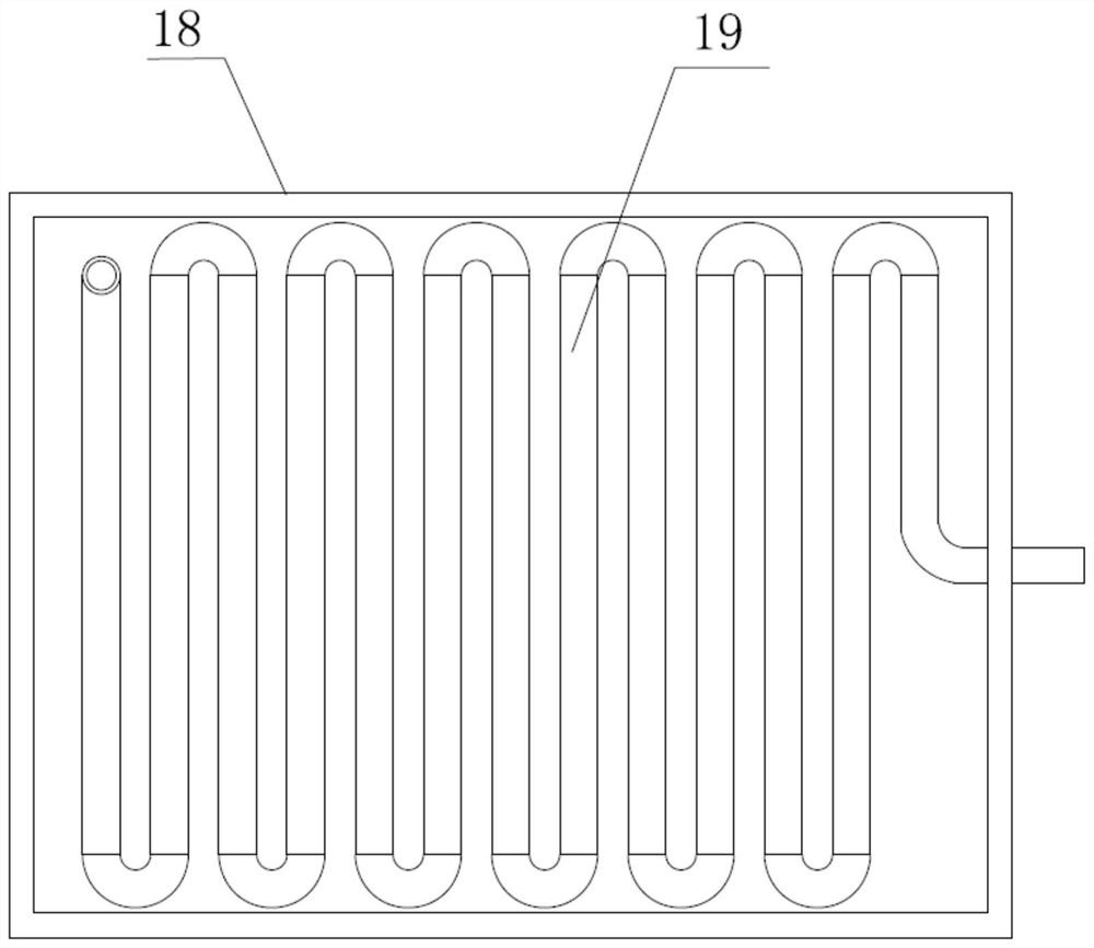
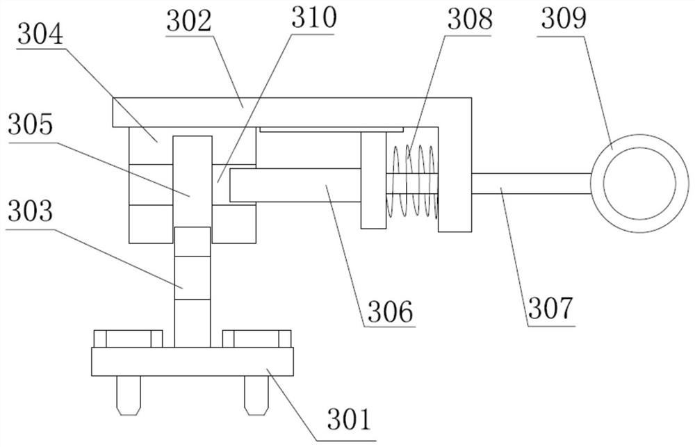
[0031] like figure 1 and figure 2 As shown, a protective device for electric power metering equipment includes a base 1, a protective cover 2 is fixedly connected to the top of the base 1, and two installation components 3 are arranged on the inner bottom of the protective cover 2, and the top of the two installation components 3 A fixed plate 4 is fixedly connected between them, and the top of the fixed plate 4 is fixed with a power metering equipment body 5;

[0032] The inner walls on both sides of the protective cover 2 are fixedly connected with connecting components 6, and the opposite sides of the two connecting components 6 are provided with adhesive pads 7, and the inner top of the protective cover 2 is fixedly connected with a movable frame 8, and the movable frame 8 is connected with a Screw mechanism, screw mechanism comprises screw mandrel 9, and screw mandrel 9 is rotatably connected between the inner wall both sides of movable frame 8, and the outer surface of...


PUM


Abstract

The invention discloses a protection device for electric power metering equipment. The protection device comprises a pedestal, wherein the top part of the pedestal is fixedly connected with a protection cover, the bottom part of the inner side of the protection cover is provided with two installation assemblies, a fixed plate is fixedly connected between the top parts of the two installation assemblies, and the top part of the fixed plate is fixedly provided with an electric power metering equipment body; and connecting assemblies are fixedly connected to the inner walls of the two sides of the protective cover, adhesive pads are arranged on the opposite sides of the two connecting assemblies, a movable frame is fixedly connected to the top part of the inner side of the protective cover, alead screw mechanism is connected into the movable frame, an air outlet nozzle is fixed to the lead screw mechanism, an air blower is fixedly connected to the top part of the outer side of the protective cover, and an air outlet of the air blower penetrates into the protective cover through an air outlet pipe and is communicated with the interior of the air outlet nozzle. The temperature controlefficiency is improved while shell protection is provided, the good high-temperature-resistant and low-temperature-resistant functions are achieved, and the service life of electric power metering equipment is prolonged.

Description

technical field [0001] The invention relates to the technical field of equipment protection, in particular to a protection device for electric power metering equipment. Background technique [0002] Electricity marketing means that in the changing market environment, in order to meet people's power consumption needs, power companies provide power products and corresponding services that meet consumption needs through a series of market-related business activities of power companies, so as to realize the business goals of enterprises. Target. The essence of electric power marketing is to adjust the demand level and demand time of the electric power market, satisfy users' reasonable electricity consumption requirements with good service quality, realize mutual coordination between electric power supply and demand, and establish a cooperative partnership between electric power companies and users. Prompt users to take the initiative to change consumption behavior and electrici...

Claims


Application Information

Patent Timeline
IPC IPC(8): H02B1/26H02B1/56H02B1/28
CPCH02B1/26H02B1/565H02B1/28
Inventor 李耀芳胡国荣谢啟华李博川温志超许一风陈志豪林彩琴罗芷彤
Owner GUANGDONG POWER GRID CORP ZHAOQING POWER SUPPLY BUREAU
Learn More