Stray emission reduction circuit

A deflection circuit, cathode ray tube technology, applied in the direction of cathode ray tube/electron beam tube, cathode ray tube indicator, circuit, etc., to achieve the effect of simple design and easy assembly

Inactive Publication Date: 2003-10-22
THOMSON MULTIMEDIA SA
View PDF2 Cites 0 Cited by
  • Summary
  • Abstract
  • Description
  • Claims
  • Application Information

AI Technical Summary

Problems solved by technology

[0008] While using a bleeder resistor has its advantages, one of the main disadvantages is the cost of installing the bleeder resistor on the FTB

Method used


Image

  • Stray emission reduction circuit
  • Stray emission reduction circuit
  • Stray emission reduction circuit

Examples


Embodiment Construction

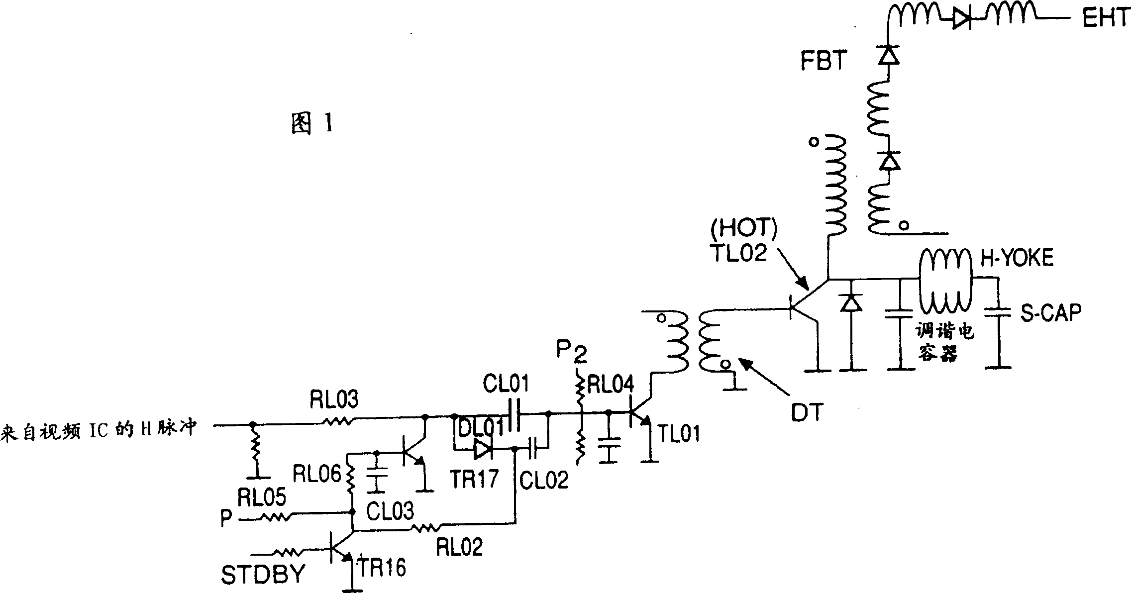
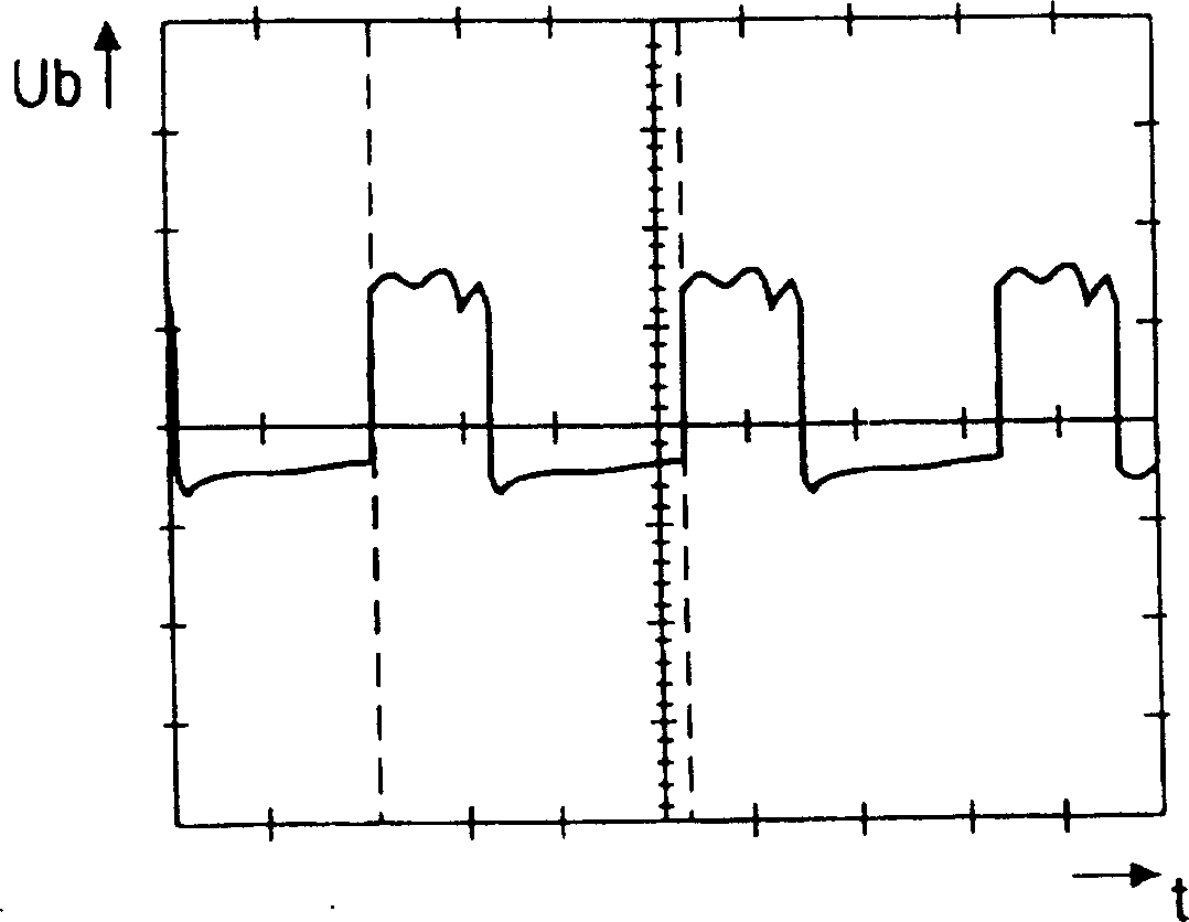
[0024] Figure 1 is used to illustrate the principle of a preferred embodiment. Under normal operation, when the television is switched on, transistor TR16 is turned on by the standby signal. This turns off TR17 and at the same time forward biases diode DL01, the H pulse for switching transistor TL01 on and off is coupled by capacitor CL02 to the base of transistor TL01. Capacitor CL02 has a higher value relative to parallel capacitor CL01. Under normal operation, the H pulse is connected and biased sufficiently at 24V to drive transistor TL01, followed by a regular switching frequency (see also figure 2 ) controls the correct switching of the HOT transistor TL02.

[0025] When the television is switched to standby mode, transistor TR16 is turned off. Therefore, due to the high voltage at point B (about 22V), diode DL01 is reverse biased. The beneficial part of the invention is that, at this moment, the H pulse is differentiated at this moment due to the small value capaci...


PUM


Abstract

A most popular method for reducing stray emission effects in a cathode ray tube is to install a bleeder resistor at the flyback transformer of the tube. Such a bleeder resistor is, however, quite expensive. Therefore, the stray emission reduction circuit according to the invention differentiates the H pulse when the TV set is switched from ''on'' to ''standby'' which results in a higher duty cycle of the control transistor, implying a lower duty cycle of the horizontal output transistor HOT. This results in a lower voltage at the tuning capacitor and hence lowers the flyback peak voltage at the anode. The results in a drop of the EHT voltage.

Description

technical field [0001] The present invention relates to a television receiver equipped with a device for preventing certain visual artifacts (such as afterglow phenomenon), and more particularly to a circuit for reducing spurious emissions in cathode ray tubes. Background technique [0002] Ghost images may appear on some used cathode ray tubes (hereinafter referred to as CRTs) when the television is switched from "on" mode to "standby" mode or "off". This effect is called stray emission or afterglow and it is usually collected on grid 1 or grid 2 of the electron mechanism (i.e. electron gun), accelerated by the anode voltage (extremely high voltage labeled EHT) and hits the CRT Particles on the fluorescent body, in other words caused by impurities. Due to current CRT manufacturing processes, it has not been possible to completely remove these particles. Manufacturers of CRTs usually guarantee that spurious emissions are suppressed if the EHT voltage is immediately discha...

Claims


Application Information

Patent Timeline
Patent Type & Authority Patents(China)
IPC IPC(8): H04N5/68G09G1/00G09G1/04H04N3/16H04N3/20H04N5/63
CPCH04N5/63H01J2229/0015H04N3/20
Inventor 许火烟黄胜发吴俊兴
Owner THOMSON MULTIMEDIA SA
Why Eureka
Try Eureka