
Automatic positioning device for movable plate feeder

An automatic positioning and feeding machine technology, applied in the direction of conveyor objects, transportation and packaging, etc., can solve the problem of major accidents such as belt corridor blockage, and achieve the effect of increased safety and reliability, improved reliability, and automatic dual positioning

Pending Publication Date: 2021-03-26
JINCHUAN GROUP LIMITED
View PDF0 Cites 0 Cited by
  • Summary
  • Abstract
  • Description
  • Claims
  • Application Information

AI Technical Summary

Problems solved by technology

After the original mobile apron feeder is moved and turned into place, positioning pins are manually inserted and dialed to ensure that the mobile apron feeder is affected by the impact force of the mine bin, and the mobile apron feeder is pushed to move automatically. The risk of major accidents caused by trolley slipping and belt corridor blockage

Method used


Image

  • Automatic positioning device for movable plate feeder
  • Automatic positioning device for movable plate feeder
  • Automatic positioning device for movable plate feeder

Examples


Embodiment Construction

[0018] The present invention will be described in detail below in combination with specific embodiments.

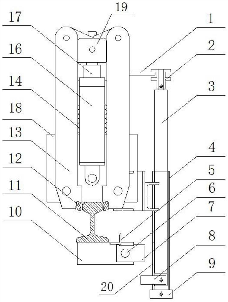
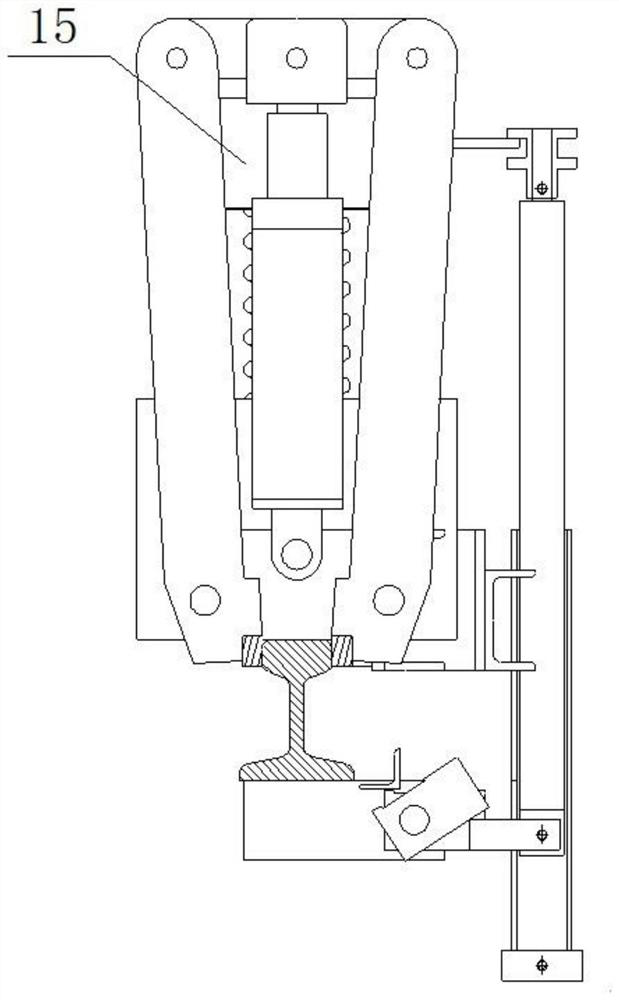
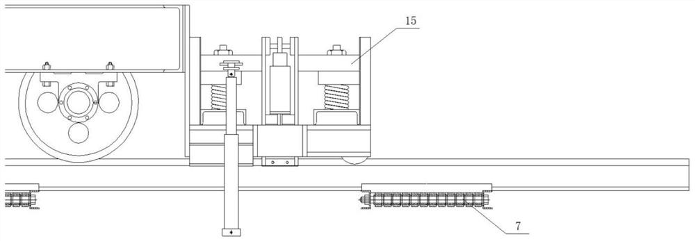
[0019] Such as Figure 1-4 As shown, an automatic positioning device for moving the apron feeder, including a jaw thrust rod 13, the bottom of the jaw thrust rod 13 is equipped with a jaw 12 for clamping the transport rail, and the middle position of the top of the jaw thrust rod 13 is It is the lifting part 19, and the lifting part 19 drives it to move up and down through the piston 17 in the hydraulic thrust rod 16. The side of the lifting part 19 is connected with a spring upper pressing plate 15, and a spring 14 is fixed between the spring upper pressing plate 15 and the base 18, and the spring 14 The compression or release is realized by the movement of the piston 17 of the hydraulic thrust rod 16; the guide plate 1 is welded on the side of the spring upper pressure plate 15, and the guide limit 2 is set on the side of the guide plate 1, and the guide plate 1 moves u...


PUM


Abstract

The invention discloses an automatic positioning device for a movable plate feeder. The device comprises a jaw thrust rod, a jaw for clamping and transporting a steel rail is arranged at the bottom ofthe jaw thrust rod, a lifting part is arranged in the middle of the top end of the jaw thrust rod, and the lifting part is driven by a piston in a hydraulic thrust rod to move up and down. A spring upper pressing plate is connected to the side portion of the lifting part, a spring is fixed between the spring upper pressing plate and the base, and the spring is compressed or released through piston movement of the hydraulic thrust rod; a guide plate is welded to the side face of the spring upper pressing plate, and a guide limiter is arranged at one side of the guide plate and shifted by the guide plate to move up and down; and the guide limiter is fixed at the top end of a guide rod, the guide rod is sleeved with a guide sleeve, the bottom of the guide rod is provided with a slider, and the slider is matched with a positioning block group arranged on the side surface of a transportation steel rail bracket. By means of the device, automatic double positioning of the movable plate typefeeder is achieved, and safety and reliability are greatly improved.

Description

technical field [0001] The invention belongs to the technical field of automatic positioning, and in particular relates to an automatic positioning device for a movable apron feeder. Background technique [0002] The mobile apron feeder is the key and commonly used equipment for unloading materials in multiple ore bins. It is widely used in cement, silicate products, new building materials, refractory materials, chemical fertilizers, ferrous and non-ferrous metal beneficiation and other production industries to unload ores and other dry materials stored in various multi-mine silos. The mobile apron feeder is suitable for unloading various multi-bin materials, and is widely used in mineral processing, building materials and chemical industries. After the original mobile apron feeder is moved and turned into place, positioning pins are manually inserted and dialed to ensure that the mobile apron feeder is affected by the impact force of the mine bin, and the mobile apron feed...

Claims


Application Information

Patent Timeline
IPC IPC(8): B65G47/20
CPCB65G47/20
Inventor 张维永周智超齐雪松
Owner JINCHUAN GROUP LIMITED
Learn More